RUBIC UNA Monitoring System

Characteristics


Properties
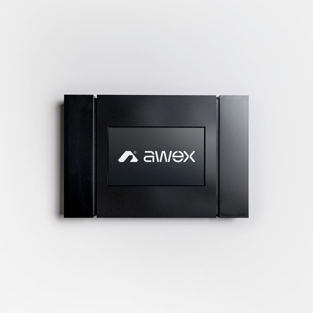
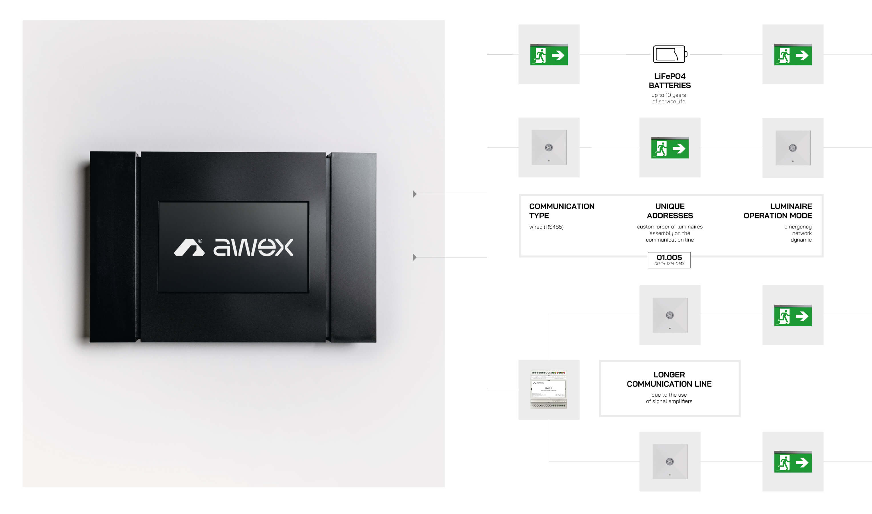
The RUBIC UNA is the latest and the most advanced monitoring system designed to control independent luminaires of emergency and escape route lighting systems. It is dedicated to small-to-medium facilities and buildings. Each control unit can handle up to 400 luminaires using MPU250 Power submodules. Submodules communicate with the RUBIC UNA via a LAN network.
RUBIC UNA has an integrated touch panel and intuitive graphic menu enabling quick and easy system configuration without the need to use external software. Each RS address module is assigned an individual number/address. The addresses are factory-assigned so no addressing unit is required for installation, setting up or maintenance work.
The applicable standards require that periodic tests of emergency lighting systems are carried out - both short functional tests and long battery performance tests – and that an event log is maintained. These events are registered in the non-volatile memory of the control unit and will not be lost even if the battery is disconnected or drained. At any time, the event log can be saved to an external SD memory card supplied with the control unit or downloaded remotely through the implemented communication protocols.
Depending on the project set up, the system may include the following components:
![]()
System Topology
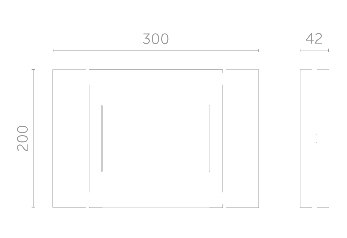
Dimensions
System components
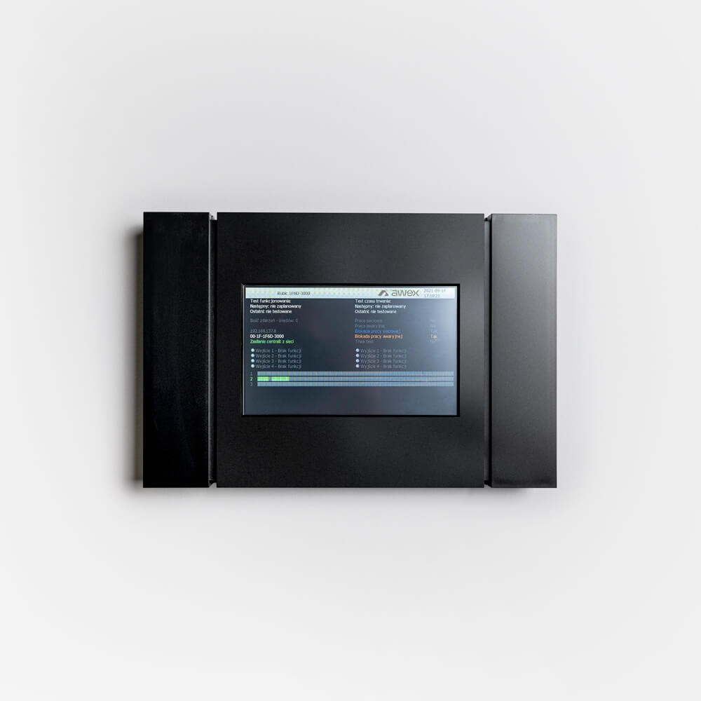
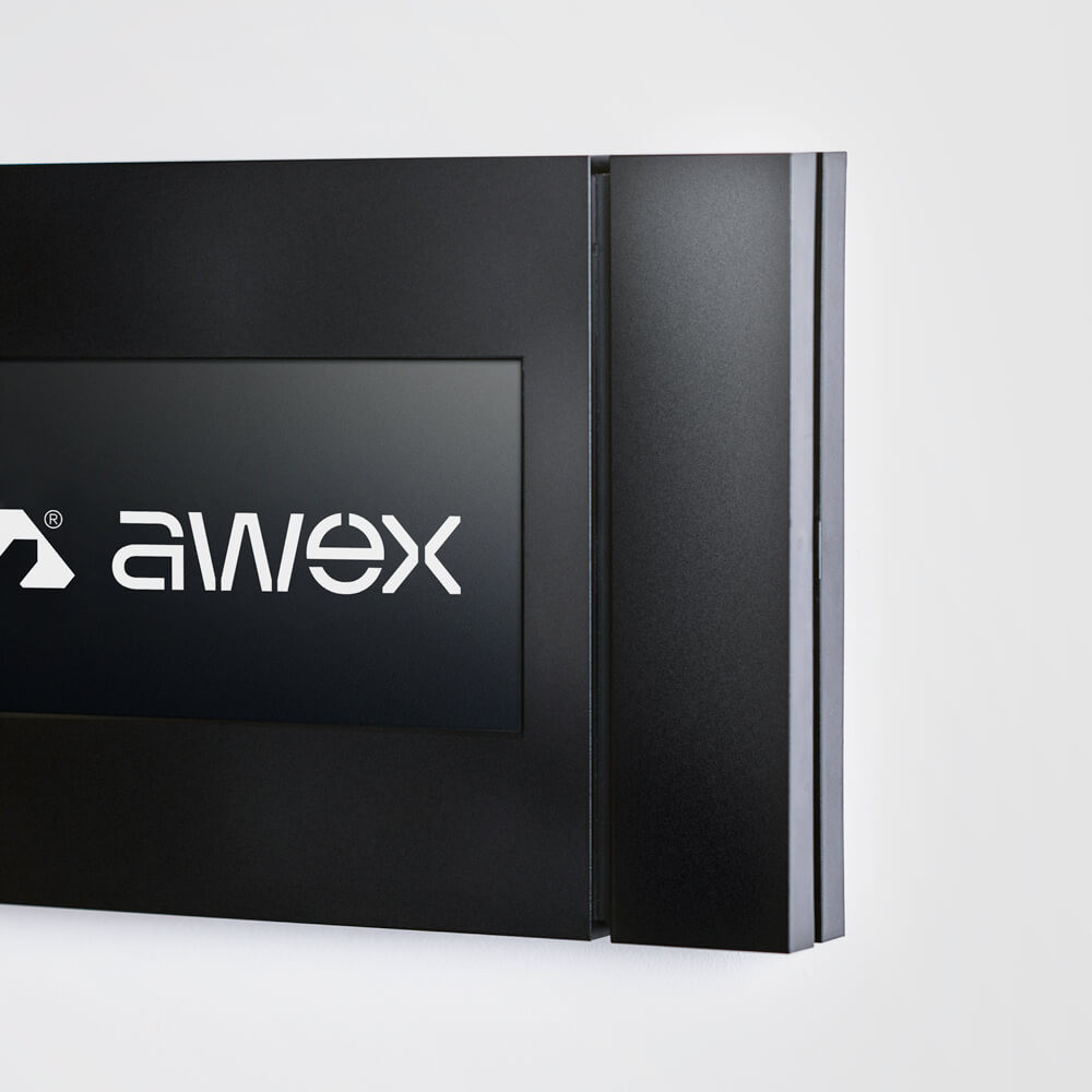
RUBIC UNA Central
The Rubic UNA control unit is designed for mounting on non-flammable flat surfaces (wall). Installation is done by screwing four wall plugs (assembly hole diameter Ø 3mm) in the specially prepared (thinned) points. The mounting locations and cable entries are covered by the elements of housing that need to be removed during installation.
The control unit is equipped with a 7" touch screen display. All necessary information about the status of the system is displayed on the main screen. Complete system configuration is possible from the main screen. Each control unit has a built-in battery to ensure that the unit can remain functional for at least 3 hours in case the mains supply is interrupted.
The RUBIC UNA control unit communicates with the user via the touch screen display. For the purposes of this solution, the intuitive menu was designed and the user may navigate through it using a number of icons and buttons that are displayed on the screen. Tapping the appropriate area within the start screen and entering the access password displays the section related to the selected parameters.
| Technical Parameters | |
|---|---|
| Supply voltage | 230V AC 50/60Hz |
| Fuse | TR5 T2,5A250V at 230VAC TR5 T2,5A250V at battery connection |
| Current rating | ~ 250 mA |
| Output voltage | 12VDC ± 25% |
| Operating temperature range | 0 oC do +40 °C |
| Insulation class | I |
| IP rating | IP 30 |
| Relative humidity range | 20-90% without water vapour condensation |
| Weight (including the battery) | 1,1 kg |
| Dimensions (L/W/H) | 300 x 200 x 41 mm |
| Internal battery | 12,8V DC 1,5 Ah LiFePO4 |
| Number of internal submodules | 3 |
| Maximum number of external submodules | 13 |
| Number of submodule channels | 2 |
| Maximum number of luminaires connected directly to the control unit | 750 |
| Maximum number of luminaires connected to the system |
4000 |
| Communication line – max length of each channel |
1200 m per channel |
| Display | 7-inch touch screen |
| Mounting | Wall |
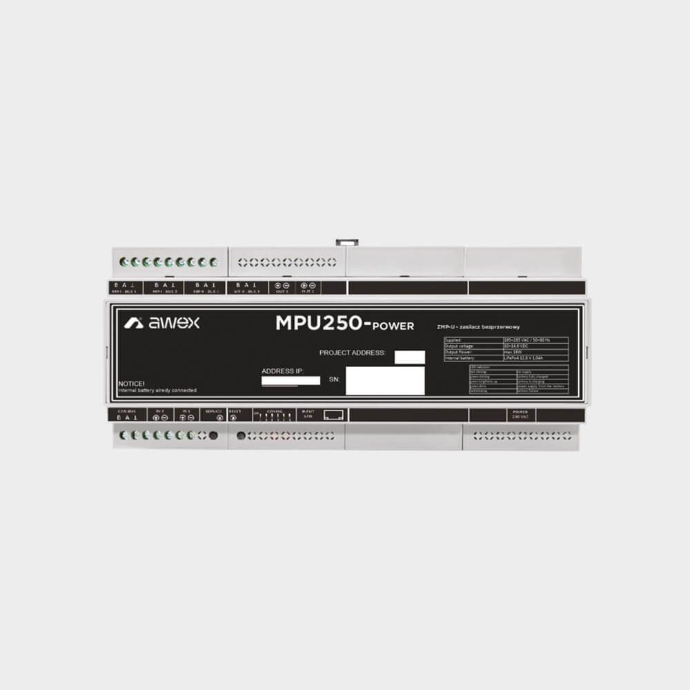
MPU250 Power Submodule
The MPU250-Power submodule is used to extend the system by adding further 250 luminaires. 13 additional external modules can be installed. The unit is designed for mounting on TH30 (DIN). The submodule communicates with the RUBIC UNA control unit via an Ethernet network, so it is necessary to connect it to the structural network of the building or to a special network dedicated to the system. The module requires that the IP address be changed to a non-factory IP address for proper operation. Each MPU250-Power module must have a distinct IP address.
| Technical Parameters | |
|---|---|
| Supply voltage | 230V AC 50/60Hz |
| Fuse | TR5 T2,5A250V at 230VAC TR5 T2,5A250V at battery connection |
| Current rating | ~ 100 mA |
| Mounting | DIN rail |
| Operating temperature range | 0 oC to +40 oC |
| Relative humidity range | 20-90% without water vapour condensation |
| Insulation class | II |
| IP rating | IP 21 |
| Dimensions (DxSxW) | 210 x 90 x 58 mm |
| IP address (default) | 192.168.137.5 |
| No of seats occupied | 12 seats (12x 17,5mm) |

MWB module
The RUBIC UNA system can handle the dynamic emergency lighting luminaires. With the use of the potential-free input module (MWB), it is possible to receive signals from the fire-protection systems and activate a pre-prepared dynamic scenario. The MWB module should be installed on the communication line in the same manner as the luminaires. The MWB can run a scenario for dynamic luminaires connected within the same submodule.
| Technical Parameters | |
|---|---|
| Supply voltage | 12 VDC |
| Current rating | 100 mA |
| Insulation class | III |
| IP rating | IP20 |
| Operating temperature range | 0 oC do +40 oC |
| Mounting | DIN rail |
| Wymiar | 105x90x58 [mm] |
| Number of inputs | 12 |
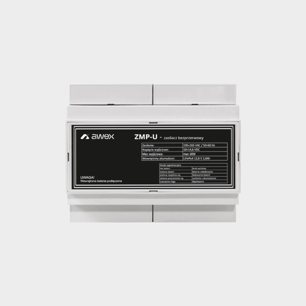
ZMPU Power Supply
The uninterruptible power supply is designed to operate with the accessories used in the RUBIC UNA system. It ensures that modules continue to run in the emergency mode. Use of UPS to supply the SWITCH secures the sending of information between a submodule and the RUBIC UNA control unit even when the primary power supply is not available.
| Technical Parameters | |
|---|---|
| Supply voltage | 230V AC 50/60Hz |
| Fuse | TR5 T2,5A250V at 230VAC TR5 T2,5A250V at battery connection |
| Current rating | 100 mA |
| Output voltage | 12VDC ± 10% |
| Operating temperature range | 0 oC to +40 oC |
| Insulation class | II |
| IP rating | IP 20 |
| Relative humidity range | 20-90% without water vapour condensation |
| Dimensions (DxSxW) | 105x90x58 mm |
| Internal battery | 12,8VDC 1Ah LiFePO4 |
| Mounting | DIN rail |
| No of seats occupied | 6 seats (12x 17,5mm) |
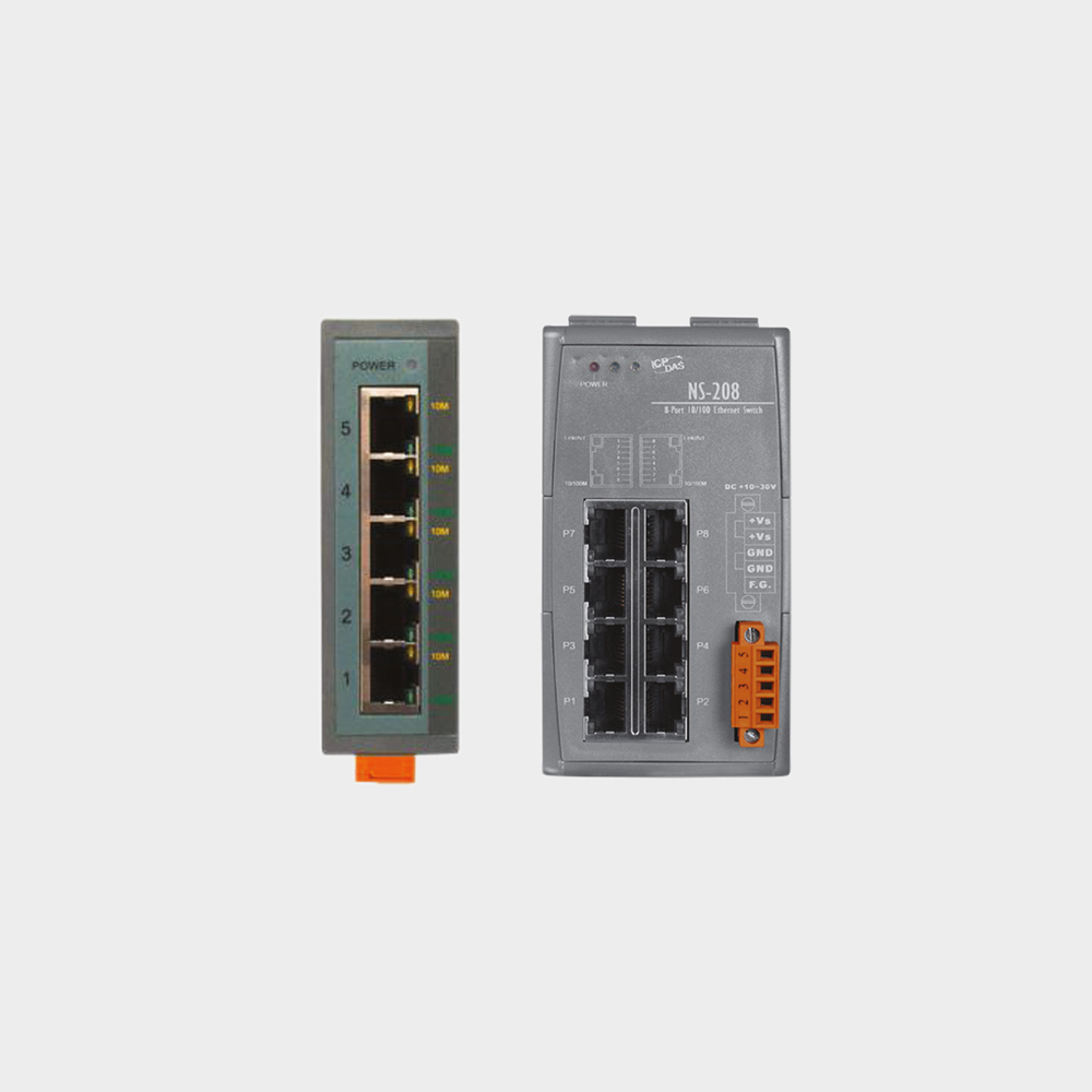
Switch RU
Each submodule communicates with the control unit via a LAN network. The maximum LAN cable is 100m. If distances are greater, a network switch is required to increase the distance by another 100m. The RU SWITCH should be provided with continuous power supply even in the case of a primary power supply failure. Absence of the guaranteed power supply eliminates communication between the MPU250-Power submodule and the RUBIC UNA control unit. AWEX offers two types of SWITCH – with 5 and 8 channels. They are designed for mounting on TH30 (DIN) rail The separation devices can be successfully supplied with the ZMPU uninterruptible power supply made by AWEX. When using a device other than the recommended one, consideration should be given to the current consumption which should not exceed 100mA. A higher current draw will reduce the back-up time of the ZMPU.
| Technical Parameters | |
|---|---|
| Supply voltage | +10 ~ +30 VDC |
| Current rating | 100 mA |
| Fuse | Protection against reverse polarity |
| Operating temperature range | 0 oC do +40 oC |
| Mounting | DIN rail |
| Dimensions (DxSxW) | 33mm x 78mm x 107mm |
Files to download

Kitemark Certificate
pdf 0.75 MB
UEA Civil Defence
pdf 2.2 MB
CE Declaration
pdf 0.4 MB