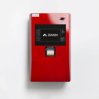
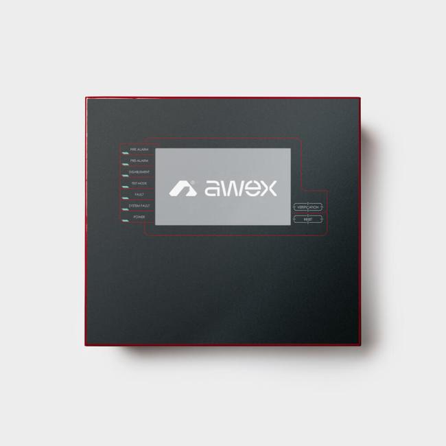
Fire Alarm Control Unit FAS

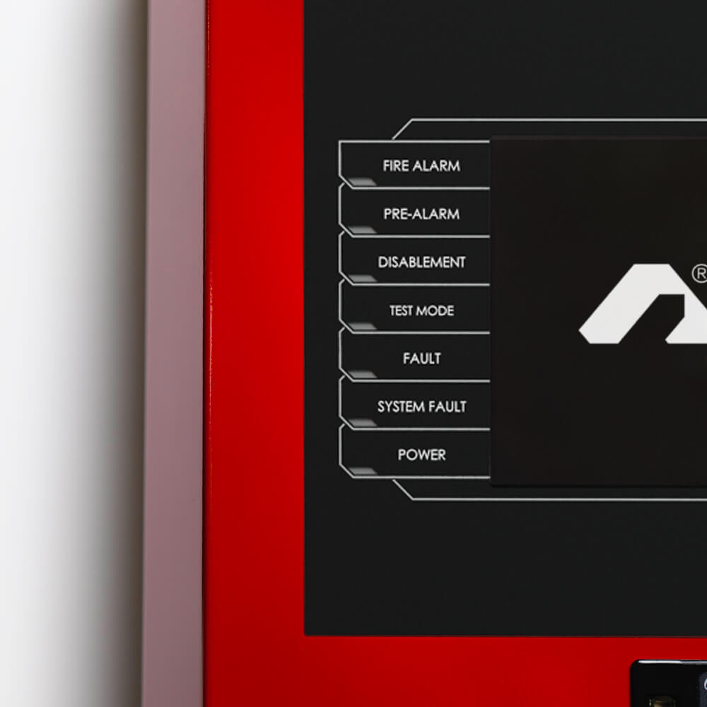
Characteristics


Properties
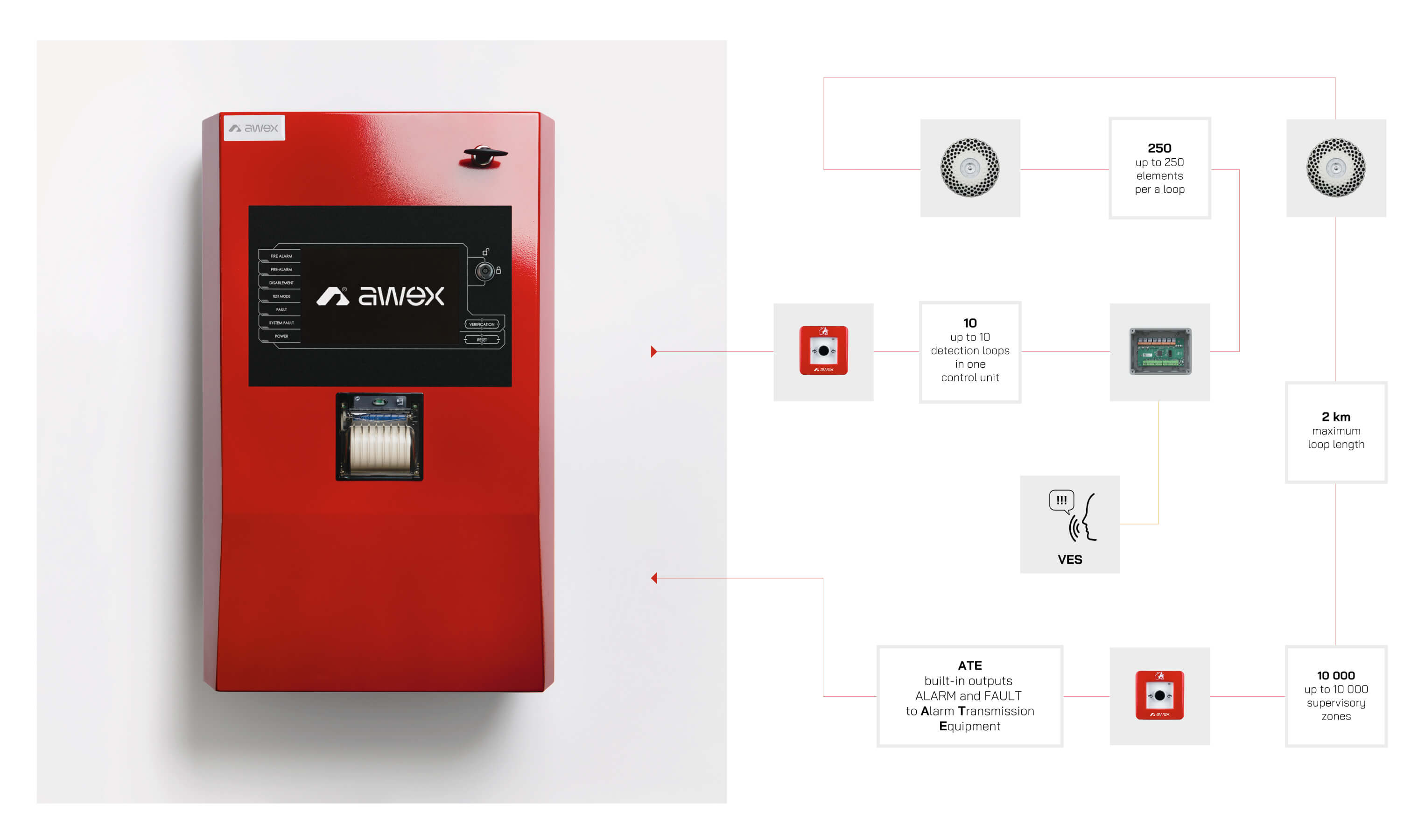
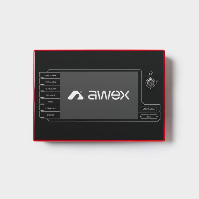
The control unit is manufactured in the module technique which makes it easy to expand and service. In the basic it has a user’s panel, a control module with a detection loop, a power supply unit and a setOptionally, the control units may be monitored through the TCP/IP protocol. Remote access to the system service is available through dedicated software or on the website.
Application of the RJ-45 connector and the IP technology allows to integrate the system and the building management systems (BMS), with the Safety management systems (SMS) and the
visualisation systems (SMART VISIO). Optionally, the control units may be monitored through the TCP/IP protocol. Remote access to the system service is available through dedicated software or on the website.
| Technical Data | |
|---|---|
| Type | addressable |
| Power supply voltage | 170-260 [VAC] 50 [Hz] |
| Power output voltage | 20-30 [VDC] |
| Batteries | 26 / 52 / 78 [Ah] |
| Wires cross-sections | up to 2,5 [mm2] |
| Detection loops wire cross-section | 0,8 – 1,5 [mm2] |
| Length of detection loop | up to 2 [km] * |
| Detection circuit types | detection loop, stub detection circuit, side stub detection circuit |
| Maximum number of detection loops | 10 |
| Maximum number of stub detection circuits | 20 |
| Maximum number of detection zones | 10000 |
| Maximum number of elements per detection loop | up to 250 * |
| Maximum number of element per stub detection circuit | 32 |
| Number of signal lines outputs | 2 |
| Alarming variants | up to 30 |
| Universal inputs | up to 12 |
| Universal relay output | up to 11 |
| Events counter | 15000 |
| Access levels | 4 |
| Printer | yes, optional |
| Lan connection | yes |
| Housing | POWDER-COATED STEEL, RAL 3000 |
| IP rating | IP 30 |
| Working temperature | 10 up to 40 [°C] |
*depends on cable type and number of elements, requires calculation during design process
![]()
System
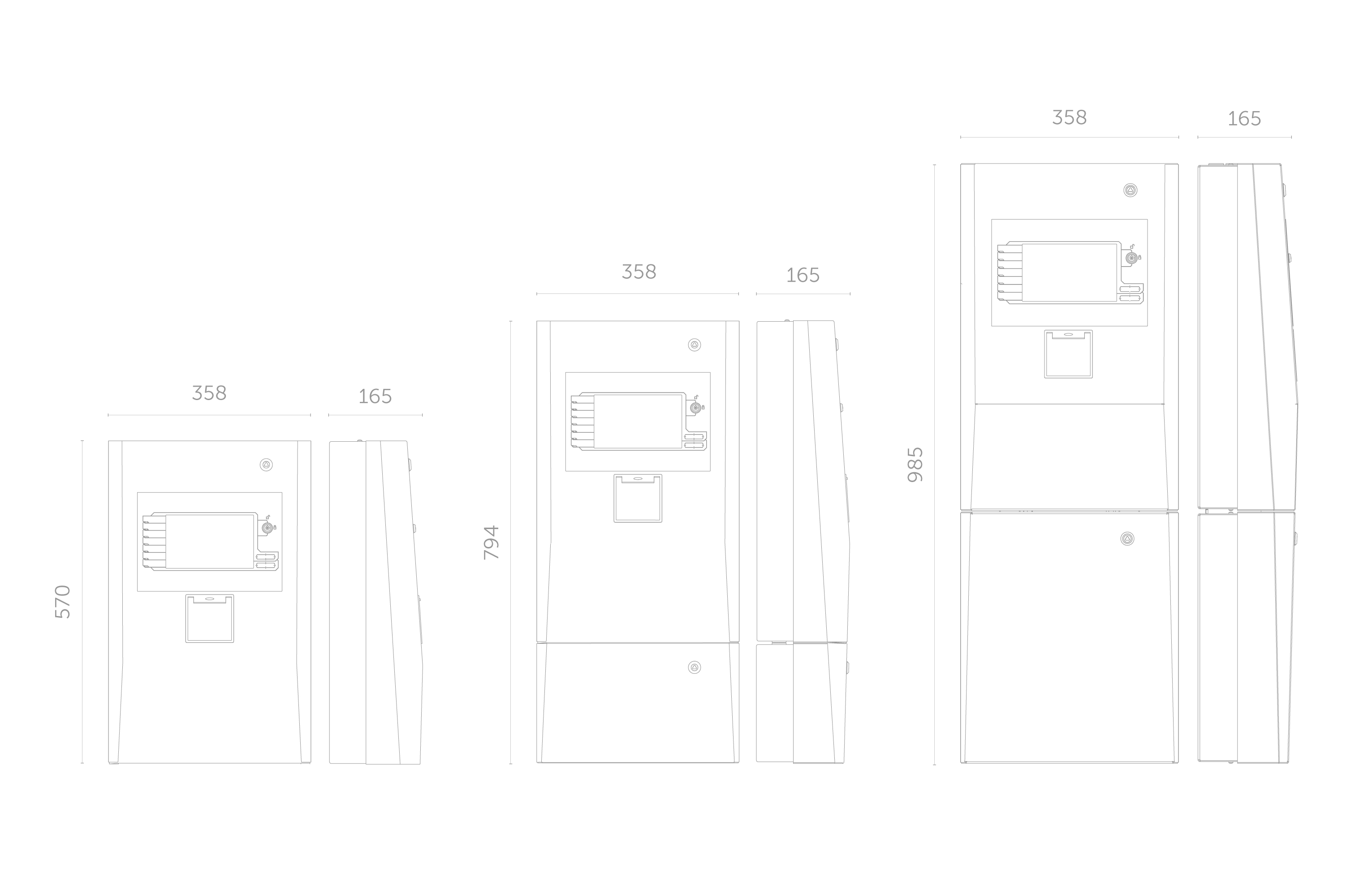
Dimensions
Extension cards
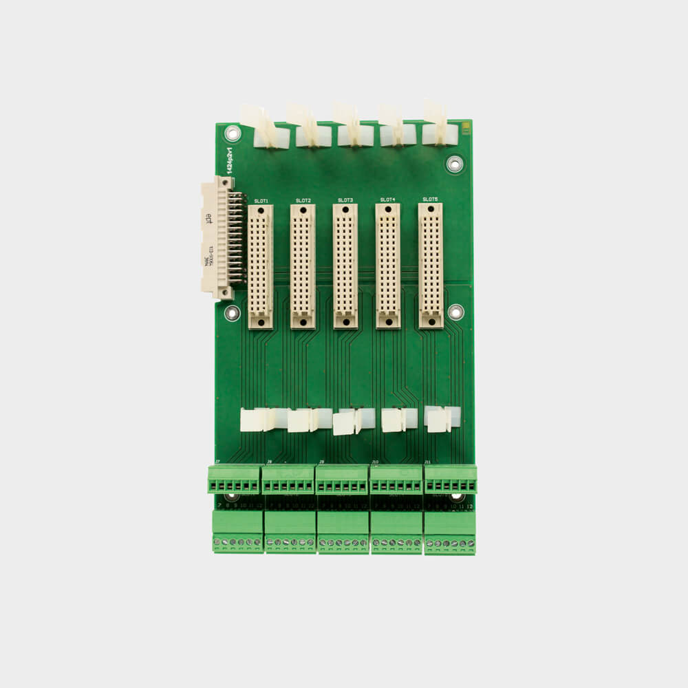
PR Slots
Extension slots PR are devices with 3 or 5 sockets for extension cards. These devices are installed inside control unit housing and they are configurable by FAS interface.
| Technical data | Extension card slot PR3 | Extension card slot PR5 |
|---|---|---|
| Assembly | Inside FAS housing | |
| Max. number of ESP | 3 | 5 |
| Product code | FSC009 | FSC010 |
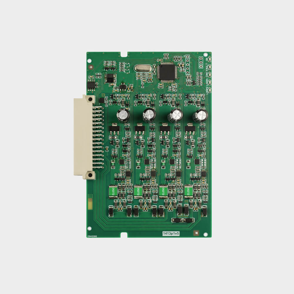
KPD2 Card
Loop detection card can be used as extension in FAS control unit. Device is connected to the extension slot PR3 / PR5. Using KPD2 we have 2 extra detection loops or 4 stub detection circuits. Card is configurable by FAS interface.
| Technical Data | Loop detection card KPD2 |
|---|---|
| Assembly | Inside fas housing |
| Number of detection loops | 2 |
| Detection circuit types | Detection loop, stub detection circuit |
| Max. Number of elements | Up to 250 per loop* |
| Max. Loop length | *up to 2 [km] |
| Max. Cards number | 5 |
| Product code | FSC004 |
*depends on cable type and number of elements, requires calculation during design process
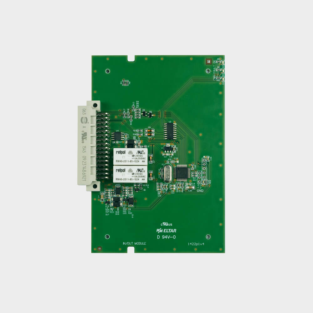
KIO22 Card
KIO card can be used as extension in FAS control unit. It has 2 supervised, dry contact inputs and 2 dry, relay outputs. Device is designed for monitoring or steering fire safety equipment or any other devices.
| Technical Data | Input output card KIO22 |
|---|---|
| Assembly | Inside fas housing |
| Number of inputs | 2 supervised inputs |
| Number of outputs | 2 relay outputs |
| Max. Output load | 30 [VDC], 0,5 [A] |
| Max. Number of cards | 5 |
| Product code | FSC005 |
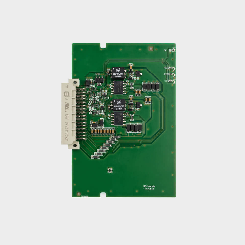
KRS Comunication cards
KRS cards are used to connecting control units in network. This helps take care of wide area buildings. Cards uses RS422 protocol. Device is connected to the extension slot PR3 / PR5, always in the last socked.
KRS 422-FO have fiber optic converter. By that device control units can be connected to network, where distance between each is up to 5 [km].
| Name | Communication card KRS 422 | Communication card KRS 422 FO | |
|---|---|---|---|
| Assembly | Inside fas housing | ||
| Max. Number of control units in network | 10 | ||
| Cable type | FTP | HTKSHekw | Światłowód wielomodowy |
| MAX.DISTANCE BETWEEN CONTROL UNITS [m] | 500 | 1000 | 5000 |
| Max. Number of external signal panel | 10 | - | |
| Product code | FSC006 | FSC007 | |
Files to download

CE Certificate
pdf 3.21 MB
CE Declaration
pdf 0.92 MB
UEA Civil Defence
pdf 1.62 MB
User Manual
pdf 4.9 MB
Configuration Manual
pdf 7.22 MB
Data Sheet
pdf 0.64 MBRelated Products
Fire Alarm Control Unit FASmini
Fire Security Systems
External Signal Panel ESP
Fire Security Systems