FZLV II Central Battery Systems


Characteristics


Properties
Due to the output voltage of 48V DC in compliance with protection class III, the FZLV II system supplies receivers with separated extra low voltage (SELV). The use of SELV voltage ensures safe operation of the system and its components in accordance with the applicable regulations. The system is equipped with its own batteries with a capacity dependent on the load and the necessary backup time of the emergency lighting.
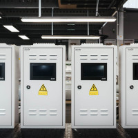
The system is provided with own batteries whose capacity depends on the load and necessary emergency lighting back-up time. It is used particularly within the designated fire zones. Compact design of the cabinet allows the installation of the system in locations where large-size central battery systems cannot be used. In addition, the small systems are enriched with the casing that meets the existing visual standards.
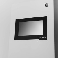
The control panel of the system has a large touch screen to allow reading the status of the system, circuits and luminaires on an ongoing basis and setting any system parameters through the interface. The statuses are displayed in the form of both graphics and text. Each luminaire in the system can be assigned a description for easy identification.
The device driver makes it possible to program and provide any configuration of the emergency and dynamic lighting luminaires. The user may choose from the following modes: non-maintained operation, maintained operation, switched mode. It is also possible to dim the individual emergency (escape) luminaires at 1% intervals in the mains supply mode. The emergency power off delay function allows leaving the emergency luminaires on for a preset time after the mains power is restored. The function of automatic searching and adding luminaires to the system does not require address to be assigned to a luminaire, as each luminaire has its unique address.
The system has a unique IP address and RJ45 connector for its direct connection to Ethernet. The built-in WEB module enables direct access to the system from any computer, including the printout of the event log using any web browser. In addition, the system is equipped with an SD card slot (card included) to save and upload the system settings (the so-called back up) and to save the Event Log reports according to PN-EN 50172. When saved on the SD card, the reports can be archived and, when necessary, printed from any PC equipped with a SD slot and printer without the need to have additional dedicated software. All settings are stored in the device’s non-volatile memory, so they are not lost even when the system is completely disconnected from the mains and battery power supply. The SD card is also used to update the FZLV II firmware, additional modules and emergency and dynamic luminaires.
Lead-acid batteries with VRLA gas recombination are designed for supplying the FZLV II cabinets and their design life time is 10 years. The operating parameters of the battery pack must comply with the technical specification, with particular regard to the operating temperature (20°C).
FZLV II system consists of:
• batteries with back-up time of 1, 3 or 8 hours
• up to 8 independent circuits, which make it possible to connect up to 20 fittings per circuit. The maximum load of a single circuit is 2.5A
• controller with a display to show the current system status and configure system parameters
• up to 8 potential-free inputs
• 2 potential inputs to supervise the power supply circuits
• 4 control outputs
• built-in memory to record the event log
• RJ-45 connector for remote communication via LAN (BACnet, Modbus, Web server)FZLV II system consists of:
![]()
System Topology

Dimensions

System components


FZLV II cabinets
The AWEX’s FZLV II is a group emergency lighting system in protection class I and intended to supply up to 160 emergency escape luminaires. Each of the luminaires connected to the system can operate independently in different switching modes.
The luminaires are supplied with safe low nominal voltage of 48V through a two-wire cable. The communication between the luminaires and the system takes place via the supply line, without use of additional communication cabling. Each luminaire (address module) has its own unique identification address. This address is assigned logically in the system and can be assigned the appropriate control.
The programmable controller shows the current status of the system and its components on the touch screen display. Using the display, each luminaire can be assigned its own description as well as its control can be changed (password required). The unit has a SD card slot to save the event log and system configuration.
Four installed programmable relay outputs allow sending the system status messages outside. The system has a built-in RJ-45 connector to enable remote access through the Web server (web page) or Smart Visio software. The system can be expanded to include a number of external modules installed on the supply lines, and this group may include input modules, output modules and phase loss sensors.
| Technical Parameters |
FZLV II – 7,2Ah |
FZLV II – 12Ah |
FZLV II – 18Ah |
FZLV II – 26Ah |
FZLV II – 33Ah |
FZLV II – 40Ah |
|
|---|---|---|---|---|---|---|---|
| Supply voltage | AC: 1-phase 230 ± 10%, 50/60Hz or DC: 216 V ± 20% | ||||||
| AC protection |
T8A/250V, 5x20 mm |
||||||
| Circuit protection |
T4A/250V, 5x20 mm |
||||||
| DC protection |
T20A/440V, 6,3x32 mm |
||||||
| Max cross-section of mains power connector |
2,5mm2 |
||||||
| Protection class |
I |
||||||
| Ingress protection |
IP20 |
||||||
| Output voltage |
48V DC ±20% |
||||||
| Working temperature |
from -5oC to 30oC |
||||||
| Dimensions |
S:650x350x150 P:680x330x150 |
S:650x350x150 P:680x330x150 |
S:870x460x220 |
S:870x460x220 |
S:870x460x220 |
S:870x460x220 |
|
| Casing |
S – Standard P – Premium |
S – Standard P – Premium |
S – Standard |
S – Standard |
S – Standard |
S – Standard |
|
| Battery capacity |
7,2 Ah |
12 Ah |
18 Ah |
26 Ah |
33 Ah |
40 Ah |
|
| No of batteries |
4 |
||||||
| Maximum power |
1 h |
166 W |
280 W |
423 W |
600 W |
734 W |
890 W |
|
3 h |
64 W |
110 W |
168 W |
241 W |
309 W |
375 W |
|
|
8 h |
25 W |
46 W |
72 W |
106 W |
137 W |
167 W |
|
| Number of circuits |
4 |
4/8 |
8 |
8 |
8 |
8 |
|
| Max. cross-section of circuit connector |
2,5mm2 |
2,5mm2 |
2,5mm2 |
2,5mm2 |
2,5mm2 |
2,5mm2 |
|
| Max circuit load* |
120 W |
120 W |
120 W |
120 W |
120 W |
120 W |
|
| Cable grommets |
24 X M20 or MC 35 multi-line |
24 X M20 or MC 35 multi-line |
MC 35 multi-line |
MC 35multi-line |
MC 35multi-line |
MC 35 multi-line |
|
| Weight |
18,5 kg |
25,5 kg |
45 kg |
52,3 kg |
60 kg |
72,5 kg |
|
*loss of power in luminaire supply cable and modules not considered

IN16F module
The IN16F module is an input device for operation between devices comprising the building installation and AWEX’s Central Battery system. It is designed to operate with the FZLV II system and supplied from its circuits. The IN16F module has 16 potential-free inputs with possibility to change the tripping logic. Data transmission between the module and the control device is carried out over the same cable that supplies power. It is possible to connect the additional panel with buttons and LEDs to signal and test correct operation of inputs.
| Technical Parameters | |
|---|---|
| Supply voltage | 32 - 56 V DC |
| Protection class | III |
| Ingress protection | IP21 |
| Working temperature | from -10 oC to +55 oC |
| Potential-free inputs | 16 |
| Input function | active, inactive, short-circuit, interval |
| Communication | power line |
| Mounting | DIN rail |
| Dimensions (LxWxD), mm | 106x90x57 |
| Connectors | 2,5 mm2 |

OUT4F module
The OUT4F module is a universal output device for operation among electrical devices, fire-fighting system and AWEX’s Central Battery system. It is designed to operate with the FZLV II system and supplied from its circuits. The OUT4F module has 4 relay outputs to control or signal any device.
| Technical Parameters | |
|---|---|
| Supply voltage | 32 - 56 V DC |
| Protection class | III |
| Ingress protection | IP21 |
| Working temperature | from -10 oC to +55 oC |
| Relay outputs | 4 |
| Output parameters | AC1 contact load: 16A / 250 V DC1 contact load: 16A / 24 V |
| Communication | power line |
| Mounting | DIN rail |
| Dimensions (LxWxD), mm | 71x90x57 mm |
| Connectors | 2,5 mm2 |

PH3F module
The PH3F module is used for monitoring 230V AC potential signals. The device can be used as a phase loss sensor or to control the emergency lighting by means of switches, according to the user’s requirements. The module has 3 potential inputs with programmable tripping logic. The inputs can be programmed so as to separately monitor the individual protections of the basic lighting circuits or as the 3PH phase loss sensor. Each of the three inputs can be assigned the power recovery delay function.
| Technical Parameters | |
|---|---|
| Supply voltage | 32 - 56 V DC |
| Protection class | III |
| Ingress protection | IP21 |
| Working temperature | from -10 oC to +55 oC |
| Potential inputs | 3 separated inputs |
| Phase loss control | possibility to monitor 3 phases |
| Communication | power line |
| Mounting | DIN rail |
| Dimensions (LxWxD), mm | 106x90x57 mm |
| Connectors | 2,5 mm2 |

CZF sensor
The CZF is equipped with a controller that checks the input voltage and compares it with the detection threshold. If the voltage value on all phases is above the threshold, the relay is switched on. The detection threshold is in the range of 138 V AC ÷ 195 V AC and complies with the standard PN-EN 60598-2-22.
Three, two-colour LED lights, labelled L1, L2, L3, are used to signal the input voltage level, an incorrect power supply level is signalled in red and a correct one in green. The yellow light indicates the status of the relay, it lights up when the relay is switched on
| Technical Parameters | |
|---|---|
| Supply voltage | 230V AC |
| Frequency | 50/60 Hz |
| Power consumption | 11 mA |
| Power | 0,8 W |
| Operating temperature range | -10 oC do +55 oC |
| Connectors | 2,5 mm2 |
| Dimensions | 90x17,5x56,4 mm |

PZS panel
The panel is intended for remote status of basic system statuses, such as mains (network) operation, battery operation, defect. Thanks to a built-in key, it is possible to lock the continuous and emergency operation. Such solution protects the system against unauthorized access. FZLV system is intended to cooperate with one PZS module. To connect two or more PZS panels to one FZLV system, it is necessary to assure special PZS panels.
| Technical Parameters | |
|---|---|
| Dimensions | 82 x 82x 55 mm |
| Supply voltage | 24V DC |
| Insulation class | III |
| IP rating | IP 41 |
| Operating temperature range | -20 oC do + 50 oC |
| Communication | changeover contact |
| Mounting | surface |
| Connectors | 1,5 mm2 |
Files to download

Kitemark Certificate
pdf 0.77 MB
UEA Civil Defence
pdf 1.09 MB
CE Declaration
PDF 0.4 MB