CBS Central Battery Systems


Characteristics


Properties
The CBS central power supply system is a an advanced, reliable and user-friendly central battery system, designed in compliance with the requirements and all important standards. The system provides the possibility of monitoring circuits, luminaires or both.
The CBS central unit is equipped with a controller that supervises the operation of the entire system and archives all information about the events that have occurred and the system state. It has an intelligent charger that supervises the entire battery charging process, which automatically stops the charging process in the event of a battery failure. Depending on the type of facility, it is possible to connect substations that diversify the functionality of the central battery system, and thus reduce installation costs by shortening the length of circuits with installed luminaires. Damage to the central unit does not result in a complete system failure, as the substations take over the control and control of end circuits and luminaires. The SD card used in the system enables the software update and the recording of the event log. All the above information is additionally stored in the controller's non-volatile memory. Thanks to the implementation of BACnet Modbus protocols, it is possible to supervise and control the system using BMS devices.
In addition, taking care of the safety of rescue teams, all CBS systems have the ability to force work in IT mode both from the level of the cabinet and by means of an external signal. Taking care of the safety of rescue teams, all CBS systems have the ability to work in IT mode both from the level of the cabinet and by means of an external signal.
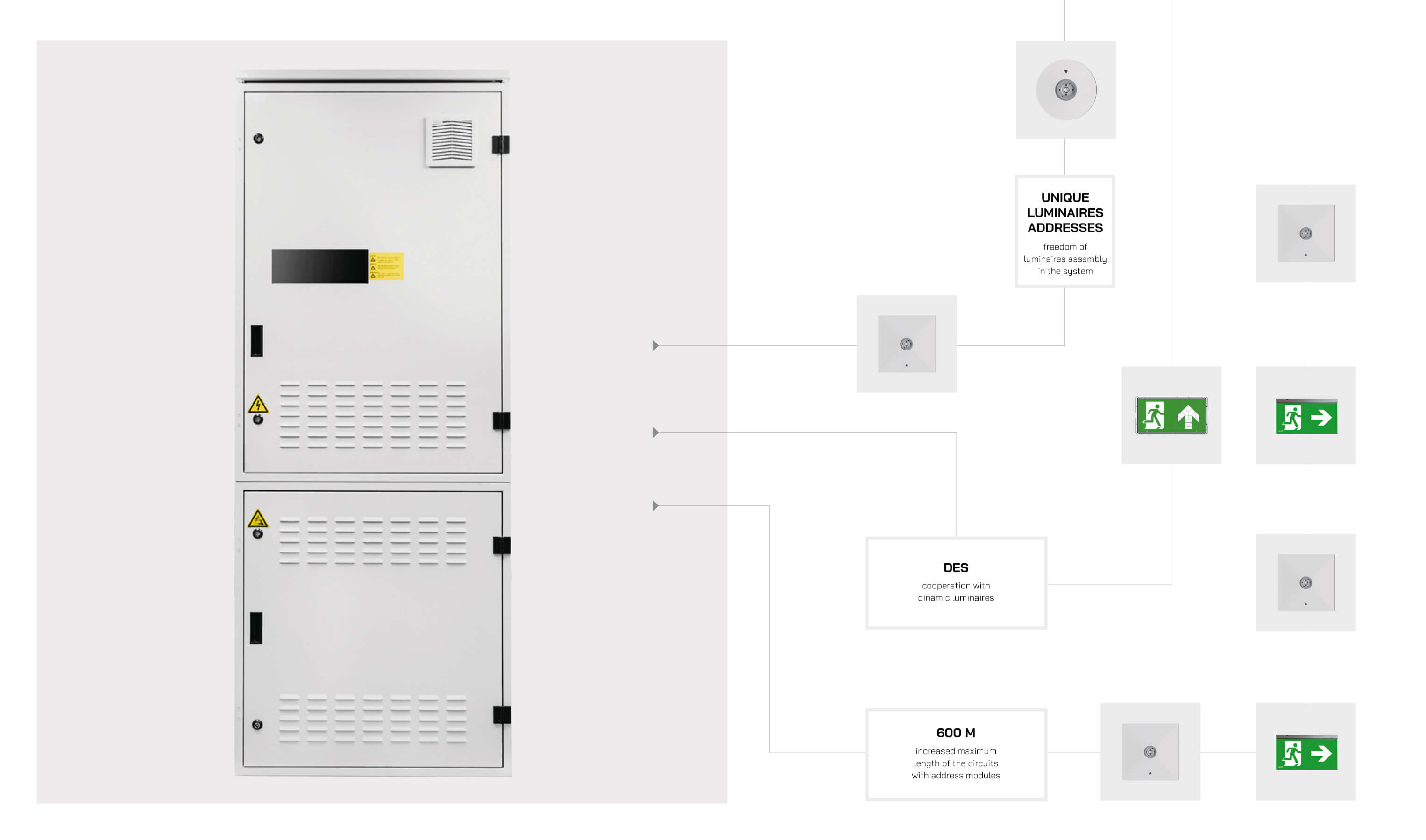
A conventional installation requires that the operating mode of each circuit is specified as early as at the design stage. Any possible changes or errors may incur extra costs or even make necessary corrections impossible. In order to eliminate such inconveniences, AWEX has introduced a new fully automatic technology to monitor and control each luminaire in a circuit.
The SMART enables installation of luminaires operating in three different modes: continuous, intermittent and switched, in a single circuit. Programming and control of the luminaires is provided by means of power supply cables and therefore no extra communication cables are required. The SMART functionality is available for luminaires fitted with appropriate address modules. The operating modes are set up from the main controller and no adjustments have to be made at the luminaires.
![]()
System Topology
Dimensions
System components

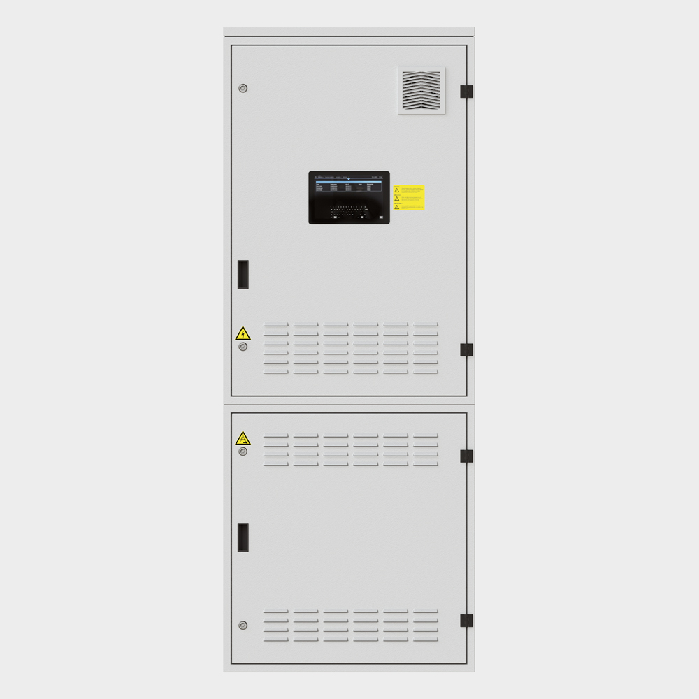
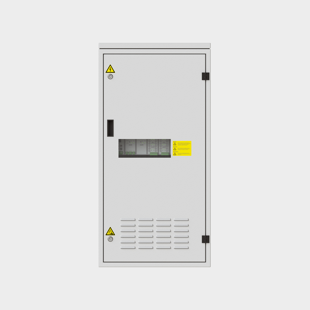
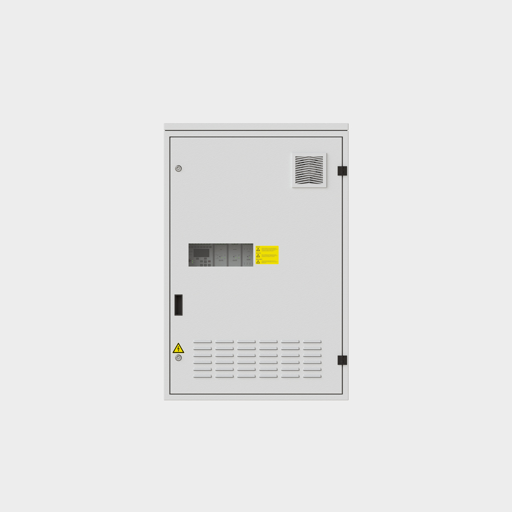
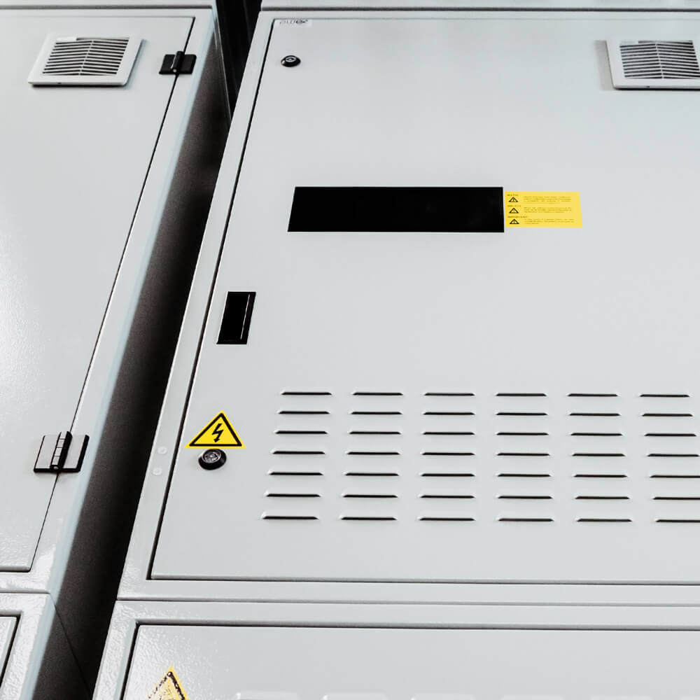
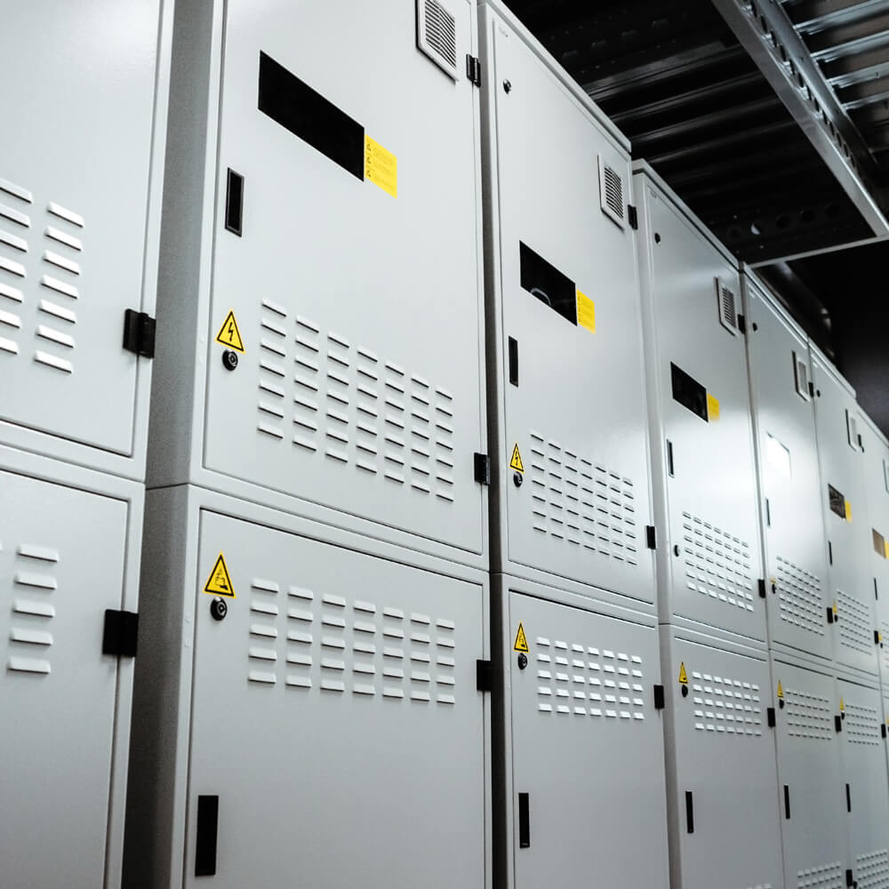
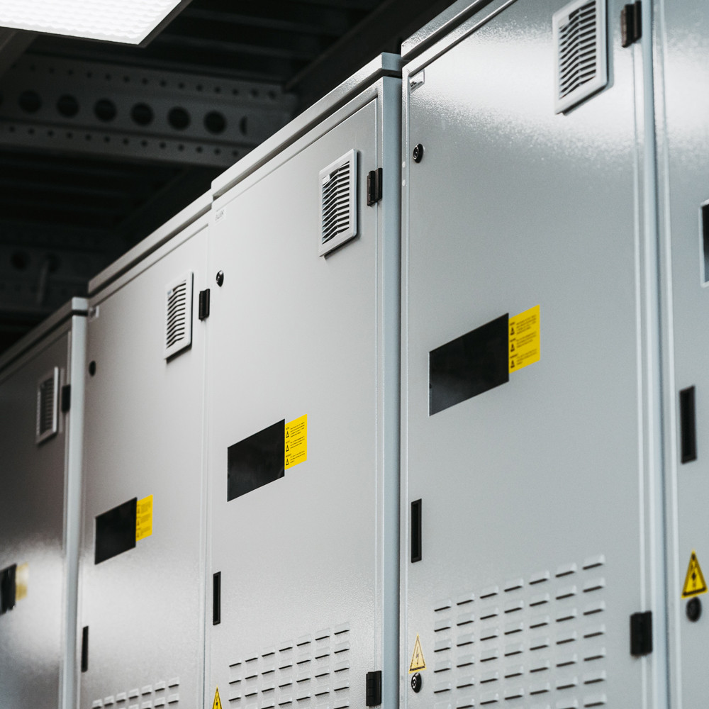
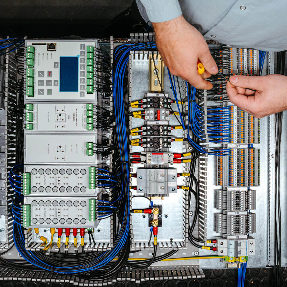
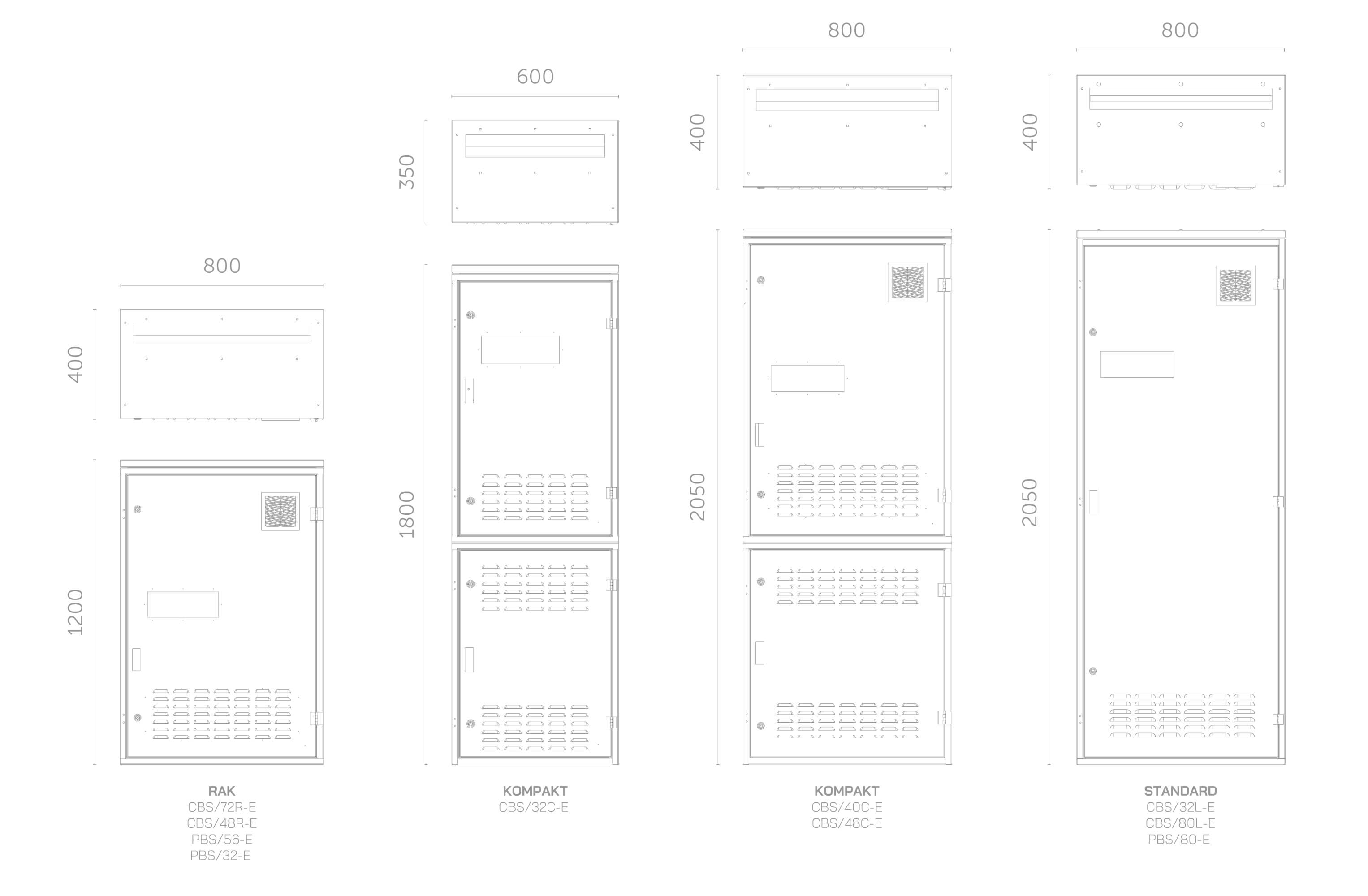
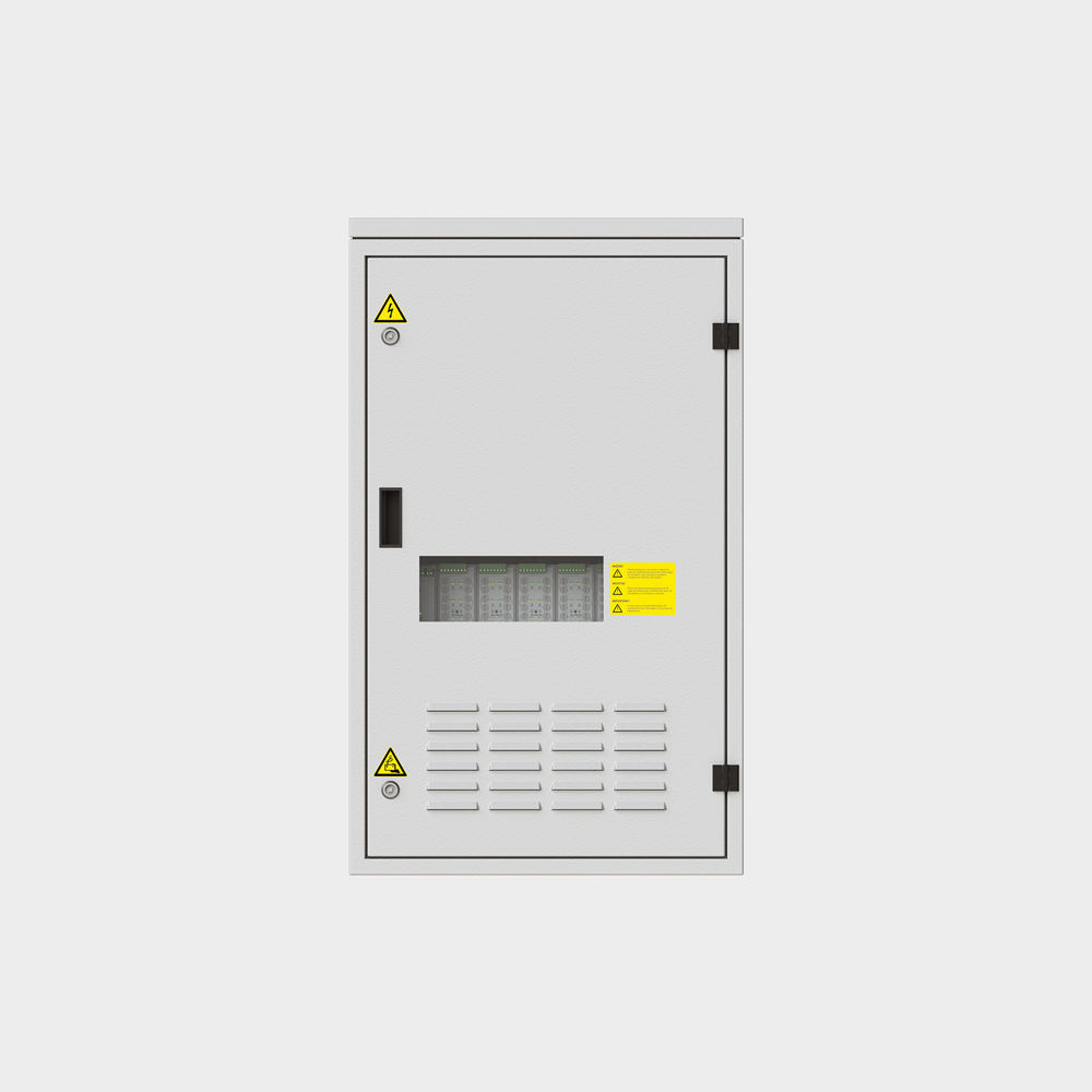
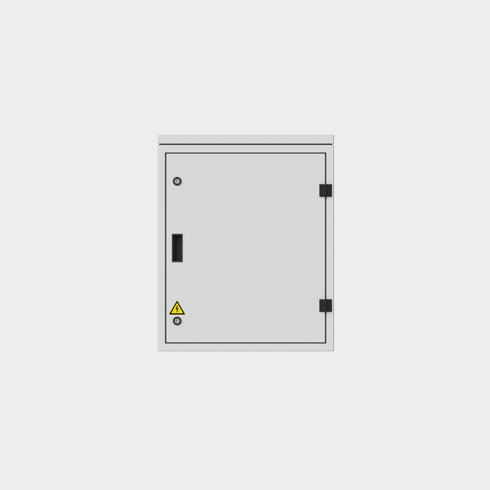
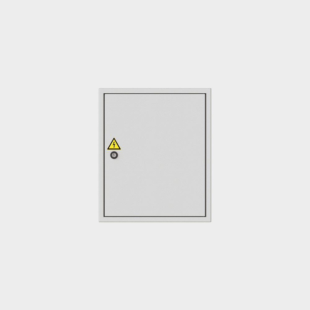
CBS cabinets
Central battery cabinets are devices made in the form of control enclosures intended for vertical placement on the ground. The doors are equipped with locks preventing unauthorized access to the interior. Inside the cabinets there is a mounting plate with the basic elements of the system. In the upper part of the housing there is a connection list for connecting power and control cables. Depending on the type of device, the battery pack may be located inside the main cabinet or in an external battery casing.
Due to the type of housing construction, CBS cabinets are divided into three types:
• Standard cabinet with the L marking
• Compact cabinet with the C designation
• RAK type cabinet with R marking
| Technical Parameters | CBS/32L-E | CBS/80L-E | CBS/40C-E | CBS/48C-E | CBS/72R-E | CBS/48R-E | CBS/32C-E | LPS/24-E |
|---|---|---|---|---|---|---|---|---|
| Supply voltage | 3 x 230V/230V | 3 x 230V/230V | 3 x 230V /230V | 3 x 230V/230V | 3 x 230V/230V | 3 x 230V/230V | 230V | 230V |
| Frequency | 50 Hz | |||||||
| Network | TN-S-C/IT | |||||||
| Dimension (HxWxD) mm | 2050x800x400 | 2050x800x400 | 2050x800x400 | 2050x800x400 | 1200x800x400 | 1200x800x400 | 1800x600x350 | 1200x600x350 |
| Housing material | steel | |||||||
| Color | RAL 7035 | |||||||
| Door type | right | |||||||
| Socle | No (1) | No (1) | No (1) | No (1) | No | No | No *(1) | - |
| Door lock | one-sided | |||||||
| IP rating | IP 30 | |||||||
| Insulation class | I | |||||||
| Cable outlets | top the bottom |
top the bottom |
top | top | top | top | top | top |
| Max. number of substations (3) | 6/2 | 6/2 | 2/- | 2/- | 2/- | 2/- | 1/- | - |
| Mains power connector cross-section | 35 mm2 | 35 mm2 | 16 mm2 (2) | 16 mm2 (2) | 16 mm2 (2) | 16 mm2 (2) | 16 mm2 (2) | 16 mm2 (2) |
| Cross-section of the battery connector | 35 mm2 | 35 mm2 | 16 mm2 (2) | 16 mm2 (2) | 16 mm2 (2) | 16 mm2 (2) | 16 mm2 (2) | 16 mm2 (2) |
| Cross-section of substation power connections | 16 mm2 | 16 mm2 | 10 mm2 (2) | 10 mm2 (2) | 10 mm2 (2) | 10 mm2 (2) | 10 mm2 (2) | - |
| Cross section of the terminal circuit connector | 4 mm2 | |||||||
| Max. circuit length | 600 m | |||||||
| Max. system power | 20 kW | 20 kW | 5,5 kW | 5,5 kW | 5,5 kW | 5,5 kW | 5,5 kW | 5,5 kW |
| Max. main fuse | 100 A | 100 A | 25 A | 25 A | 25 A | 25 A | 25 A | - |
| Max. substation fuse | 63 A | 63 A | 10 A | 10 A | 10 A | 10 A | 10 A | - |
| Max. battery fuse | 100 A | 100 A | 50 A | 50 A | 50 A | 50 A | 50 A | - |
| Max. number of circuits | 32 | 80 | 40 | 48 | 72 | 48 | 32 | 24 |
| Compact cabinet | No | No | No | No | No | No | No | No |
(1) Optionally, it is possible to equip the cabinets with 10 cm or 20 cm high socle
(2) The special design of the cabinet will enable the introduction of larger diameter connections with a limited number of substations
(3) Optionally, the number of substations depends on the type of supply (1xPH / 3xPH)
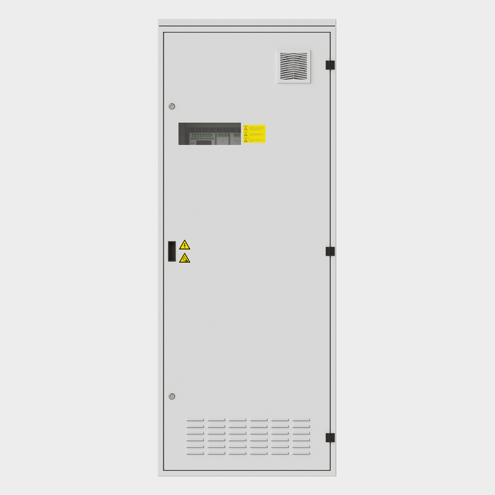
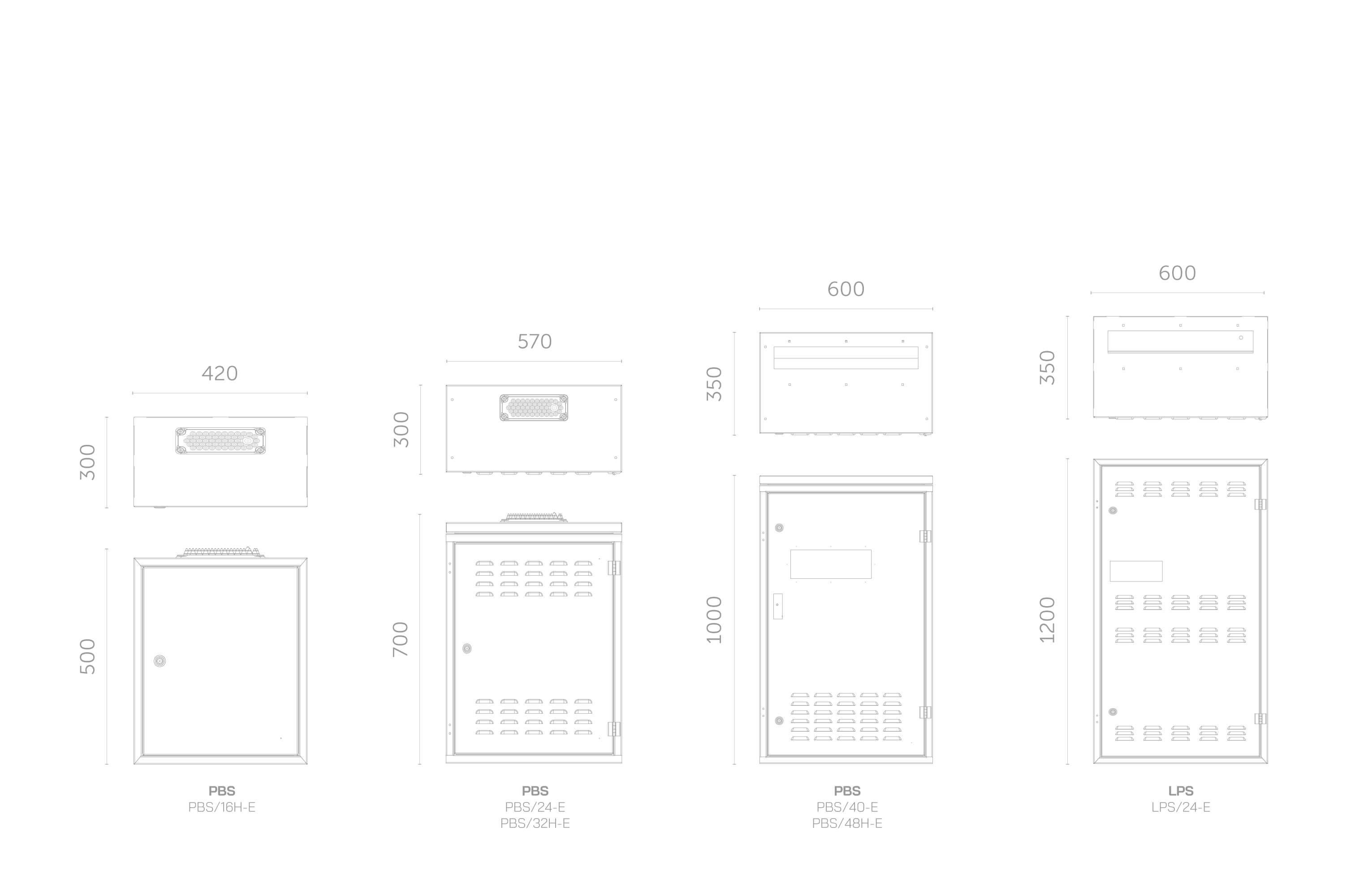
PBS substations
The CBS system can be flexibly adapted to each facility by diversifying the power supply to fire zones or the methods of routing emergency lighting circuits by using appropriate CBS systems with PBS substations. Damage to the central unit controller does not cause a complete failure of the system, because the substations take over the control and control of end circuits and luminaires, which significantly affects the safety level of the facility.
Due to the type of control unit, PBS substations are divided into two types:
• substations with a CM-NET control unit
• substations with a HUB control unit and the designation H
| Technical Parameters | PBS/80-E | PBS/56-E | PBS/32-E | PBS/40-E | PBS/24-E | PBS/48H-E (3) | PBS/32H-E | PBS/16H-E |
|---|---|---|---|---|---|---|---|---|
| Supply voltage | 3 x 230V/230V | 3 x 230V/230V | 230V | 3 x 230V/230V | 230V | 230V | 230V | 230V |
| Frequency | 50 Hz | |||||||
| Network | TN-S-C/IT | |||||||
| Dimension (HxWxD) mm | 2050x800x400 | 1200x800x400 | 1200x800x400 | 1000x600x350 | 700x570x300 | 1000x600x350 | 700x570x300 | 500x420x300 |
| Housing material | Steel | |||||||
| Color | RAL 7035 | |||||||
| Door type | Right | |||||||
| Socle | No (1) | - | - | - | - | - | - | - |
| Door lock | One-sided | |||||||
| IP rating | IP 30 | |||||||
| Insulation class | I | |||||||
| Cable outlets | top the bottom |
top | top | top | top | top | top | top |
| Max. number of substations (3) | - | - | - | - | - | - | - | - |
| Mains power connector cross-section | 35 mm2 (2) | 16 mm2 | 16 mm2 (2) | 16 mm2 (2) | 16 mm2 (2) | 16 mm2 (2) | 16 mm2 (2) | 16 mm2 (2) |
| Cross-section of the battery connector | 35 mm2 (2) | 16 mm2 | 16 mm2 (2) | 16 mm2 (2) | 16 mm2 (2) | 16 mm2 (2) | 16 mm2 (2) | 16 mm2 (2) |
| Cross-section of substation power connections | - | - | - | - | - | - | - | - |
| Cross section of the terminal circuit connector | 4 mm2 | |||||||
| Max. circuit length | 600 m | |||||||
| Max. system power | 17 kW | 11 kW | 11 kW | 11 kW | 8 kW | 11 kW | 8 kW | 5,5 kW |
| Max. main fuse | 80 A | - | - | - | - | - | - | - |
| Max. substation fuse | - | - | - | - | - | - | - | - |
| Max. battery fuse | 80 A | - | - | - | - | - | - | - |
| Max. number of circuits | 72 | 56 | 32 | 40 | 16 | 40 | 20 | 12 |
| Compact cabinet | - | - | - | - | - | - | - | - |
(1) Optionally, it is possible to equip the cabinets with 10 cm or 20 cm high socle
(2) The special design of the cabinet will enable the introduction of larger diameter connections with a limited number of substations
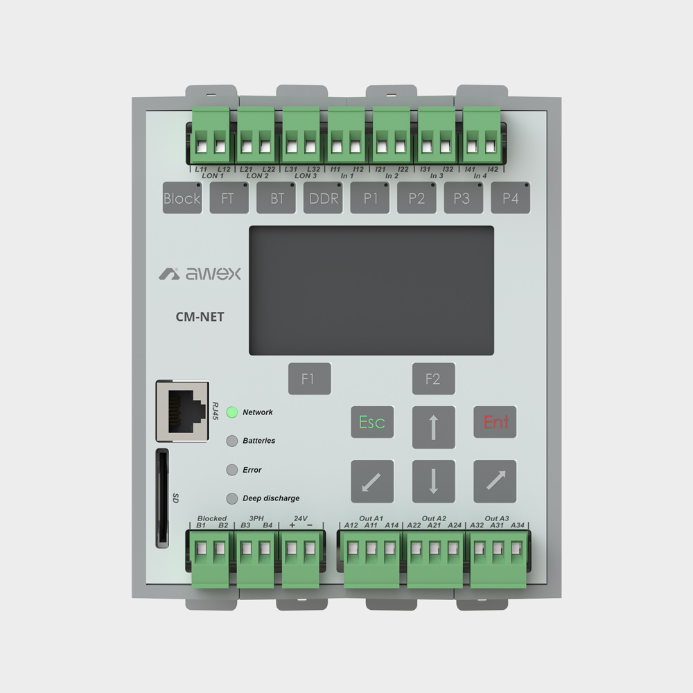
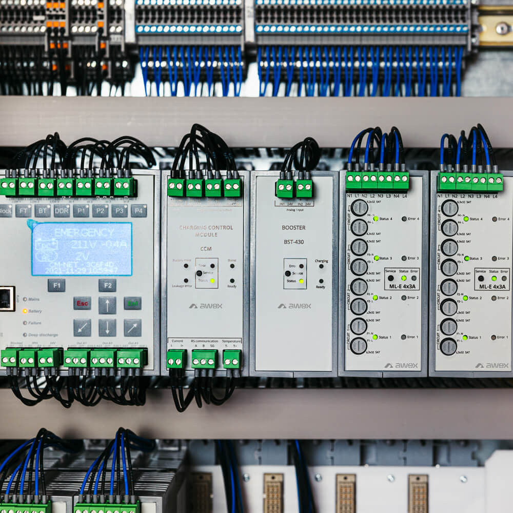
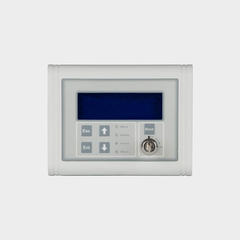
CM-NET controller
The control module is used to supervise and manage the operation of other modules within the central battery. The keyboard and LCD display in the front panel allow the user to configure and operate the whole system. The system configuration may also be carried out via RJ45 connector using SmartVISIO application installed on a computer.
Front panel LEDs allow the operational status of the central battery to be evaluated visually. The module automatically supervises the following: mains/battery mode of operation, battery charging, current, system voltage, insulation condition, deep discharge protection. Any detection of a failure or error is signalled immediately and entered into the event log. The appearance of a short-circuit or break in communication cables results in automatic switching of all circuits into emergency operation mode.
In addition, the module allows automatic searching for and adding any luminaires connected to the system. The controller allows upgrading firmware of any modules managed by it. The use of the timer allows changing the mode of luminaire operation in accordance with the assigned and configurable program. The controller is provided with programmable function buttons to allow, among other things, entering the system into service operation mode.
| Technical Parameters | |
|---|---|
| Display: | graphic LCD with a resolution of 128x64 |
| Keyboard: | 8 function keys and 8 control keys |
| LED indicators: | 4 signaling LEDs |
| Interfaces | SD/MMC |
| RJ45 - BACnet | |
| LON x 3 - Lonworks | |
| Potential-free inputs: | blockade |
| phase loss sensor | |
| 4 freely programmable inputs | |
| Outputs: | 3 programmable relay outputs |
| 24V/0,5A | |
| Sound signaling: | buzzer |
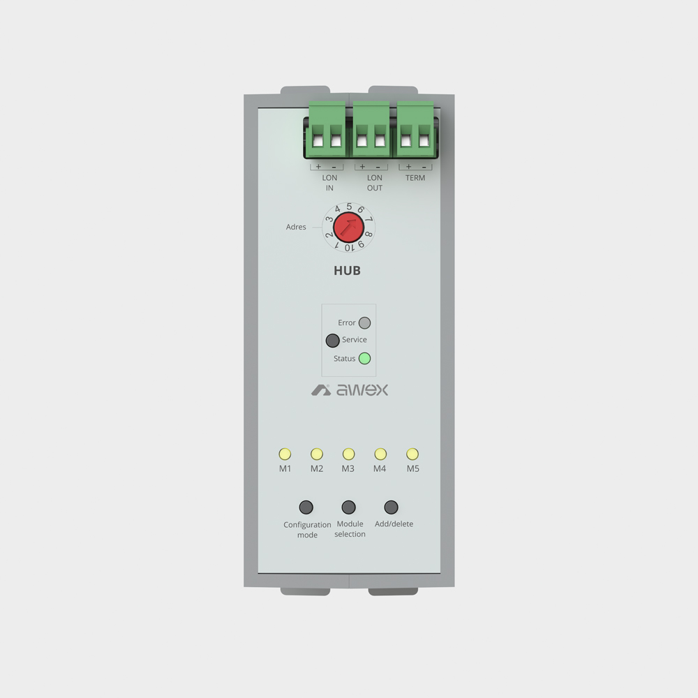
HUB module
Lon HUB module is a sub-assembly of the central battery system. It is installed in dedicated substations (ex. PBS-48H-E). Lon HUB module provides communication between CM-NET control module and the linear modules installed in substations (remote cabinets). LON3 interface is used for communication with the main cabinet. HUB supplies and communicates up to 5 linear and sensor modules. There can be a maximum of 10 HUB modules in the CBS system.
| Technical Parameters | |
|---|---|
| Number of addresses | 10 |
| Number of supported modules | 5 |
| Connectors | LON we – bus input LON3 LON wy – bus output LON3 Term – for bus termination activation LON3 |
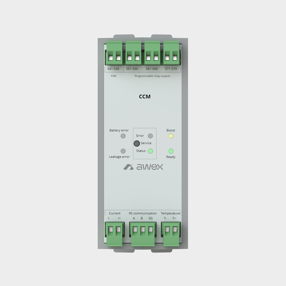
CCM module
The charger module provides the control of charging and control of batteries based on the characteristics of charging (UI) with temperature compensation according to PN-EN 50171 standard. The algorithm of charging realized by the charging control module is supervised by the control module. Charging of the batteries is realized by the BST 430 booster modules working together with the charging control module. The system can include only one module of charging control and it can work with max. 16 boosters.
During charging, it provides information for the connected boosters and controls the charging process on a regular basis. For systems including the IBMS system, it provides a communication interface that connects both systems. Apart from the function related to battery charging, the module ensures continuous monitoring of the insulation between battery circuits and PE line.
| Technical Parameters | |
|---|---|
| LED indicators | battery error |
| leakage error | |
| error | |
| status | |
| boost | |
| Deep discharge protection | 183,6 VDC |
| Outputs | 3 programmable relay outputs 1 fan output |
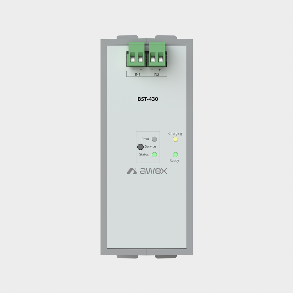
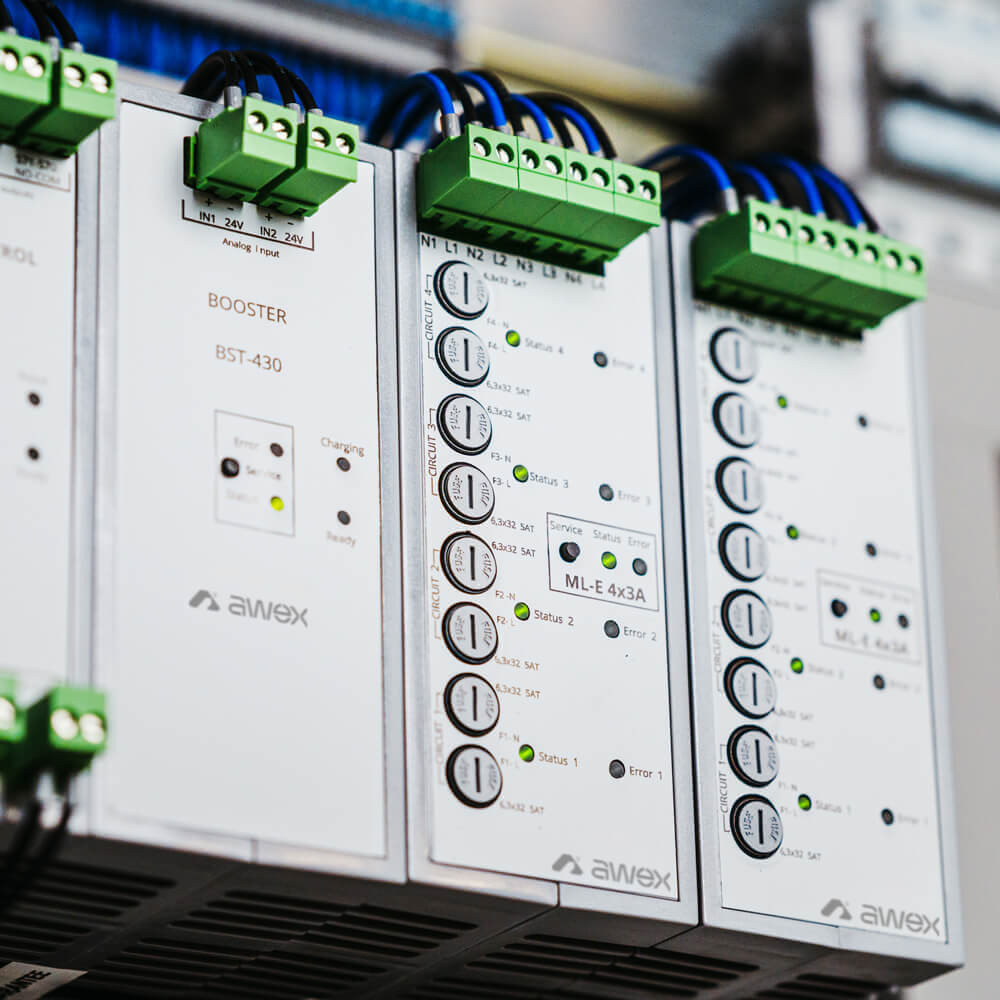
BST module
| Technical Parameters | |
|---|---|
| Charging voltage | 265V DC (boost charging) |
| 246V DC (float charging) | |
| Maximum power | 430W ± 5% |
| Maximum current | 2A ± 5% |
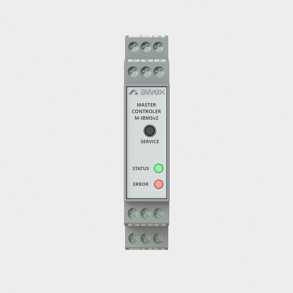
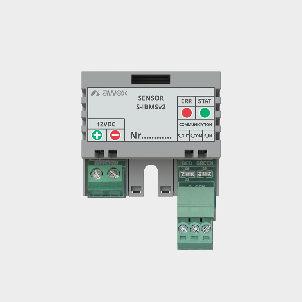
IBMS system
| Technical Parameters | S-IBMS | M-IBMS |
|---|---|---|
| Supply voltage | 5V - 20V DC | 24V DC |
| Insulation class | III | |
| IP rating | IP21 | |
| Operating temperature range | 0 oC - 50 oC | 0 oC - 35 oC |
| Dimensions (SxWxG) | 40 x 36 x 15 [mm] | 90 x 60 x 17,5 [mm] |
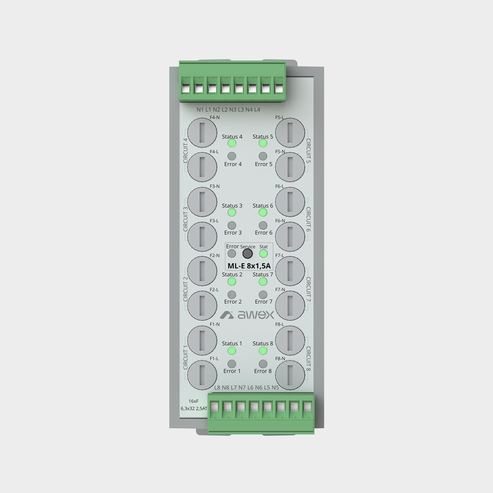
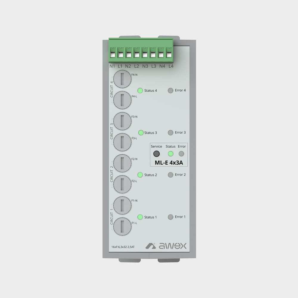
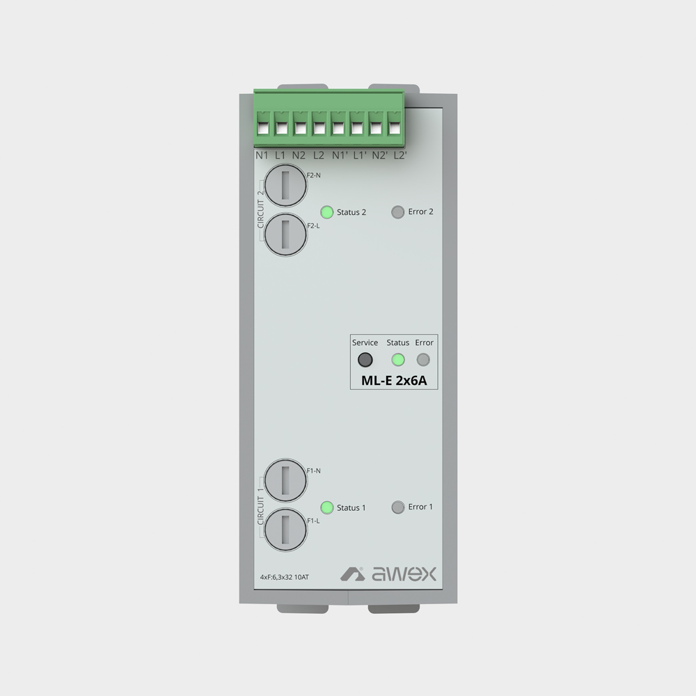
ML-E modules
Linear modules in 2x6A, 4x3A and 8x1.5A versions are used to supply 2, 4 and 8 final circuits, respectively. The devices can be used both for systems with circuit current monitoring and for systems with luminaire monitoring in SMART technology. They monitor up to 20 luminaires on each of the power lines. They enable free programming of the operating mode and control of individual luminaires. The modules have signaling diodes indicating the operating status and possible device errors.
| Technical Parameters | ML-E 2x6A | ML-E 4x3A | ML-E 8x1,5A |
|---|---|---|---|
| Number of circuits | 2 | 4 | 8 |
| Continuous operating current per circuit | 6A | 3A | 1,5A |
| Maximum starting current | 180A/ms | ||
| Switch-over time | 100 - 2500ms | ||
| Fuse | 2x10AT / 250V / 6,3x32 | 8x5AT / 250V / 6,3x32 | 16x2,5AT / 250V / 6,3x32 |
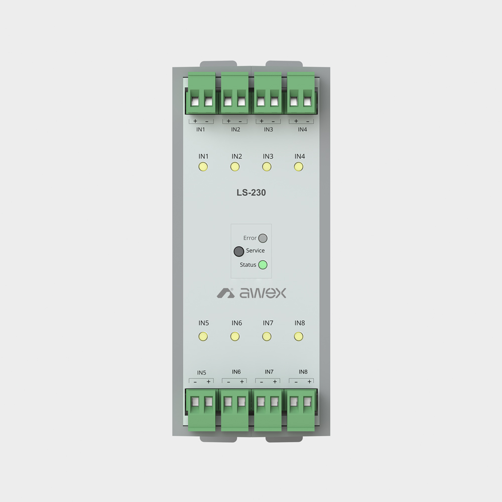
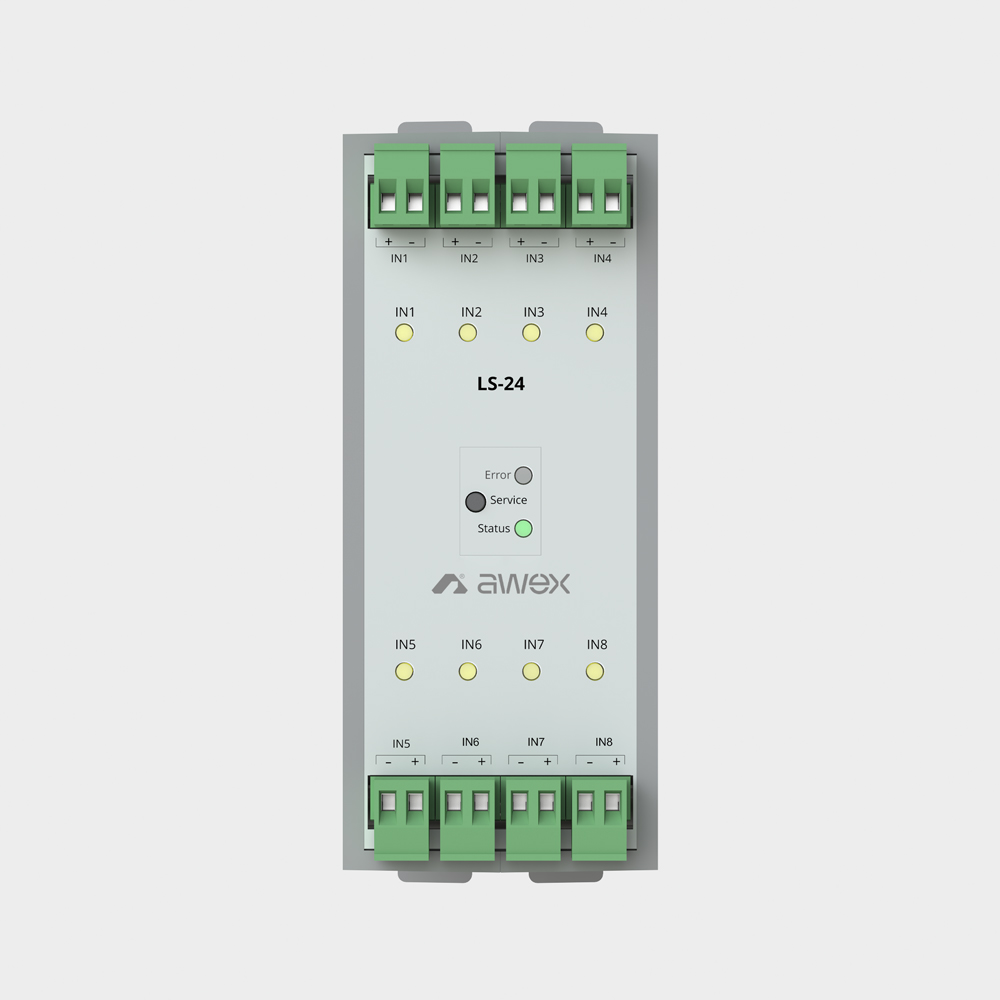
LS modules
Sensor modules LS-24 and LS-230 monitor up to 8 potential-free or potential 230V AC inputs. These inputs allow for selective activation of groups controlling luminaires by assigning them to phase loss sensors in the case of LS-24 modules or direct monitoring of basic lighting circuits with the use of LS-230. The sensor inputs have a configurable operating logic.
LS-230 enables switching groups controlling emergency lighting fittings together with supplying primary lighting circuits. Using the LS-24 module and connected to it phase failure sensors, voltage loss in the primary lighting switchboard will turn on the luminaire with the control groups assigned to them. The inputs can also be used as potential-free inputs to BMS management systems to activate individual control groups.
| Technical Parameters | LS-24 | LS-230 |
|---|---|---|
| Number of inputs | 8 wejść pętli prądowych 24V | 8 wejść potencjałowych 230V 8 wejść potencjałowych 230V |
| Delay | A return delay from 1 second to 1 hour can be set for each input. | |
| Input logic | NO, NC, RSER, RPAR | NO, NC |
| Connectors | 2,5 mm2 | |
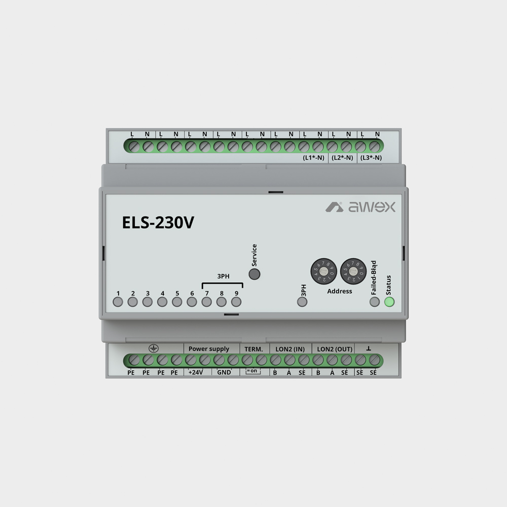
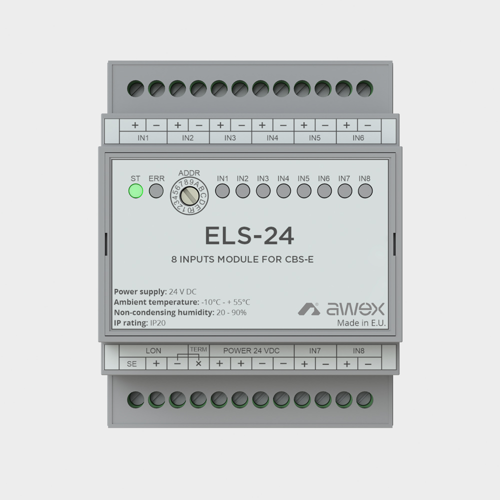
ELS modules
The ELS-24 module has 8 potential-free parameterized inputs with the possibility of programming the operating functions. The ELS-230 module has 9 monitored potential inputs. Each input can be reversed to monitor individual circuit protections, the last three inputs can be used as a 3ph phase loss sensor. Each input can be set to a return delay from 1 s to 1 hour. The maximum number of modules communicating via the LON protocol is 32.
| Technical Parameters | ELS-24 | ELS-230 |
|---|---|---|
| Supply voltage | 24V DC | |
| Insulation class | I | |
| IP rating | IP21 | |
| Operating temperature range | -10 oC do + 40 oC | |
| Input | 8 potential-free | 9 potential |
| Switching thresholds | Compliant with EN 60598-2-22 | |
| Dimensions (SxWxG) | 71 x 90 x 57 [mm] | 105 x 85 x 60 [mm] |
| Communication | LON | |
| Number of modules | Max 32* | |
| Connectors | 2,5 mm2 | |
* max. number of addresses reserved for LON modules
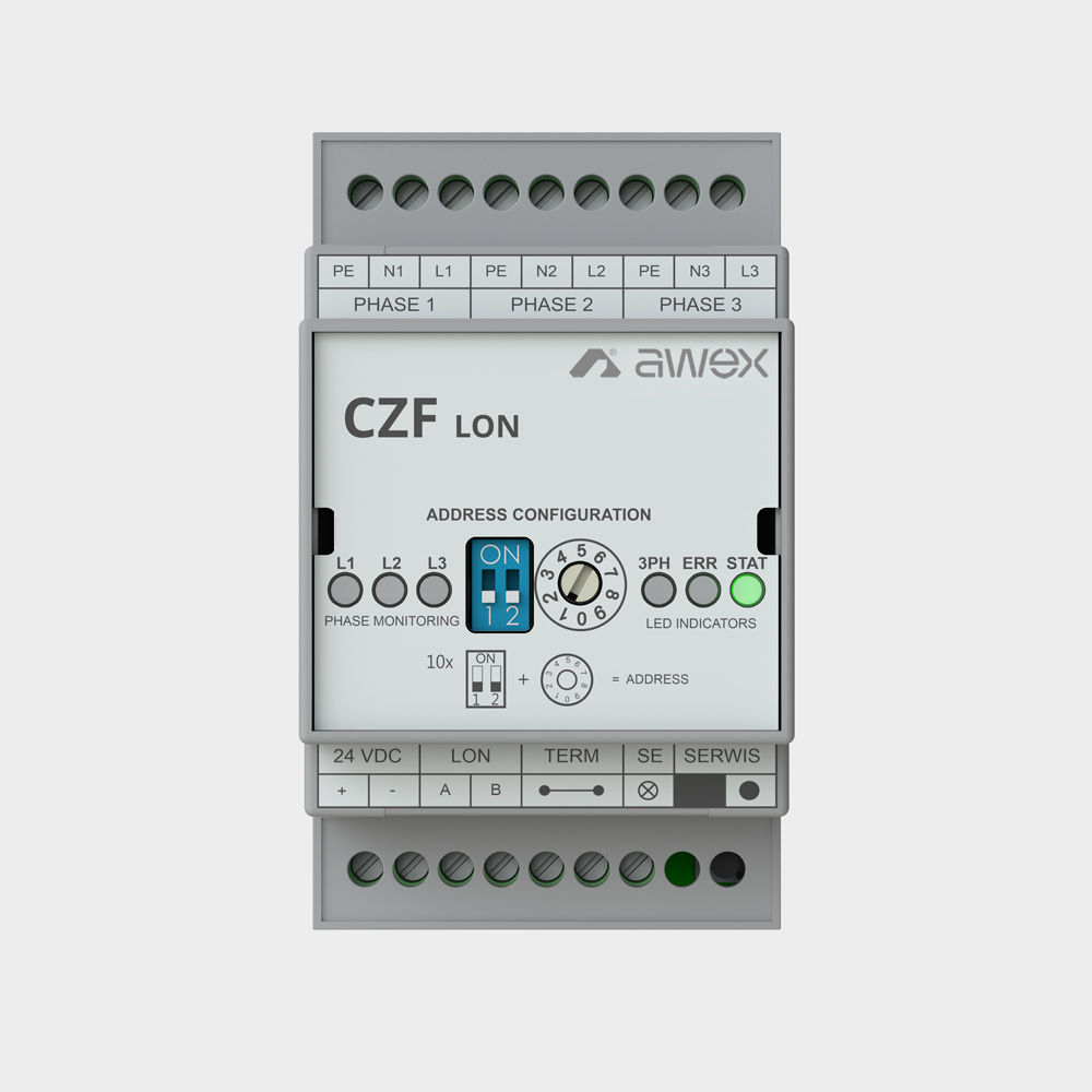
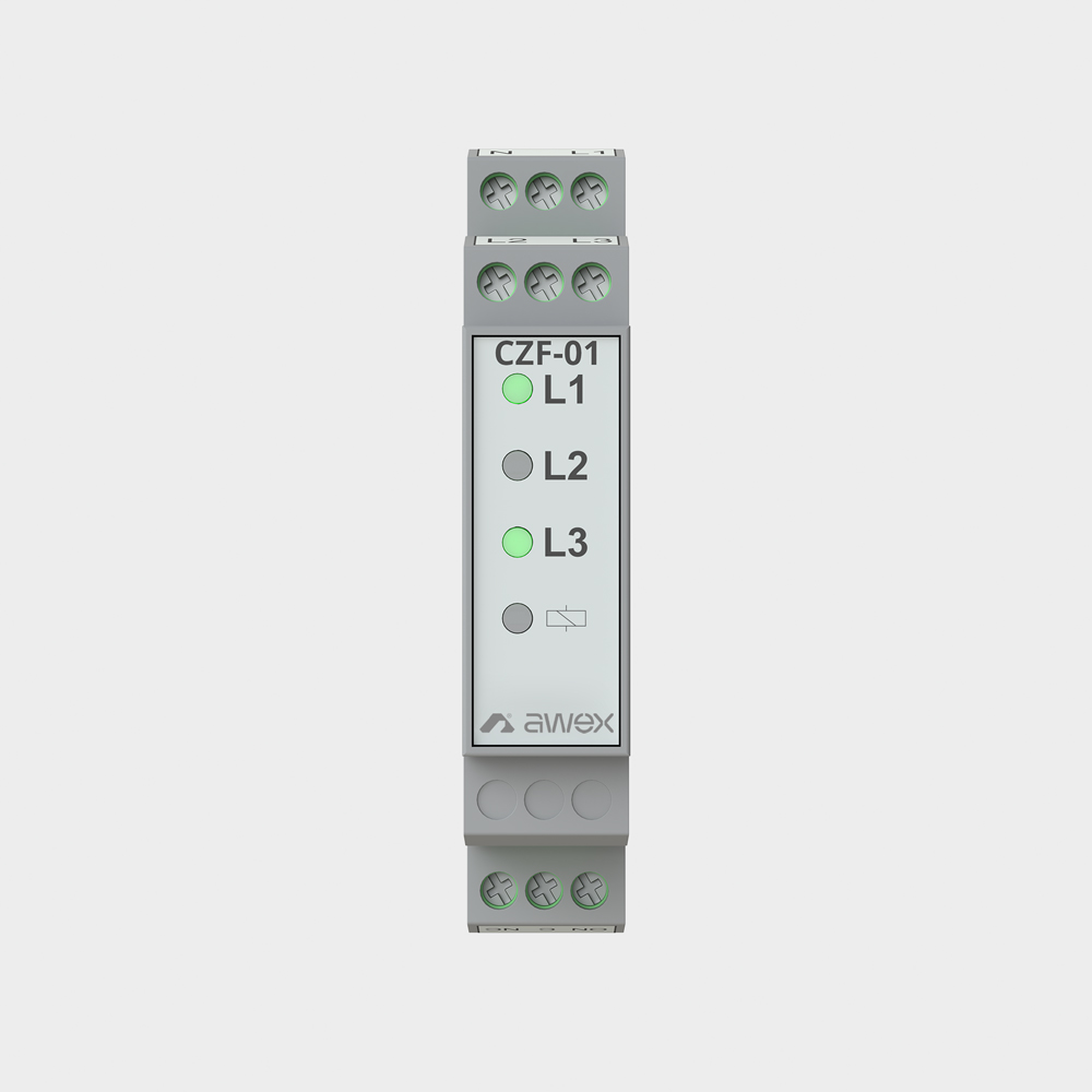
CZF modules
The CZF is equipped with a controller that checks the input voltage and compares it with the detection threshold. If the voltage value on all phases is above the threshold, the relay is switched on. The detection threshold is in the range of 138 V AC ÷ 195 V AC and complies with the standard PN-EN 60598-2-22.
Three, two-colour LED lights, labelled L1, L2, L3, are used to signal the input voltage level, an incorrect power supply level is signalled in red and a correct one in green. The yellow light indicates the status of the relay, it lights up when the relay is switched on.
The CZF LON detector has 3 monitored inputs that can work in groups as a 3ph phase loss sensor or somehow separated control inputs. Each input can be set to a delay from 1 second to 1 hour. Signals from the device are transferred to the CBS system via the LON communication protocol. The module is equipped with LED indicators informing about the current status of the module, error, logic (negation) status for individual groups, and the status of individual inputs.
| Technical Parameters | CZF | CZF-LON |
|---|---|---|
| Supply voltage | 230V AC | 24V DC |
| Insulation class | I | |
| IP rating | IP21 | |
| Operating temperature range | -10 oC do + 40 oC | |
| Inputs | 3 potential | |
| Switching thresholds | Compliant with EN 60598-2-22 | |
| Dimensions (SxWxG) | 17 x 90 x 60 [mm] | 55 x 85 x 60 [mm] |
| Communication | changeover contact NO/NC | LON |
| Number of modules | Max 32* | |
| Connectors | 2,5 mm2 | |
* max. number of addresses reserved for LON modules
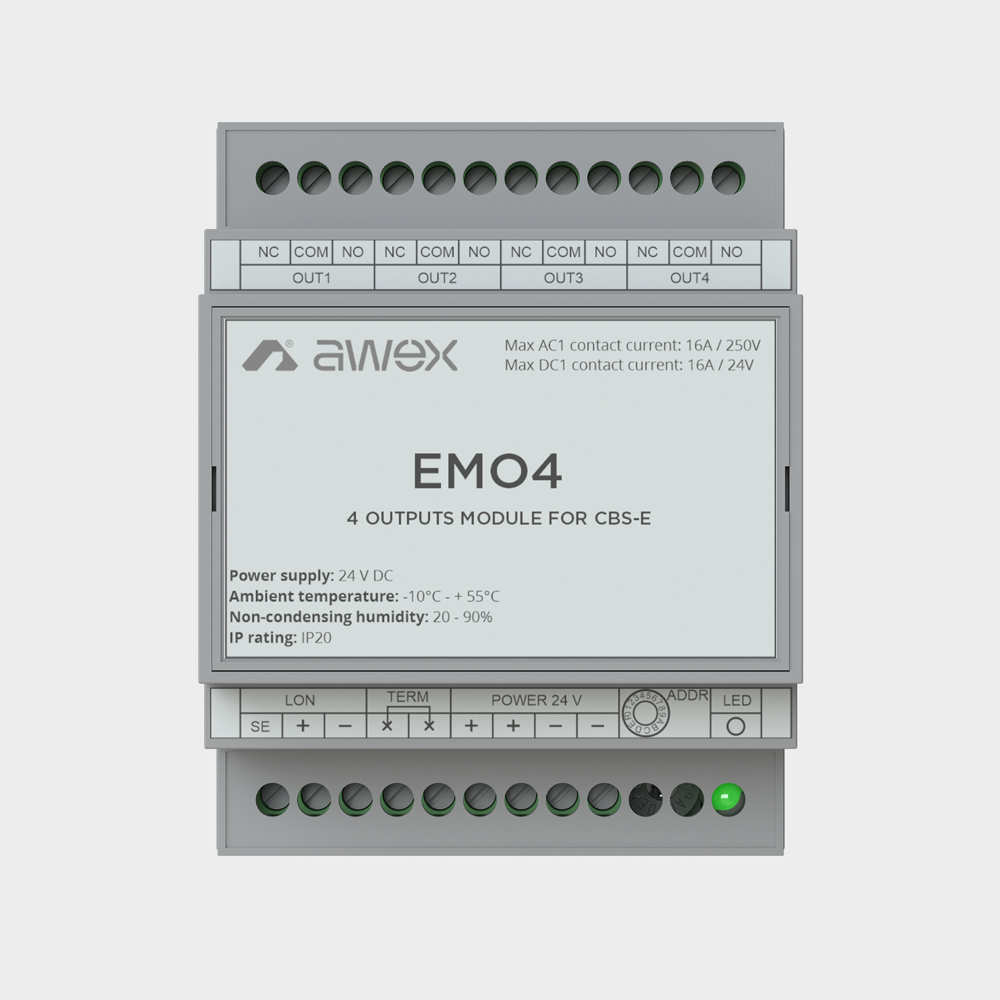
EMO4 module
The following functions can be programmed for the control outputs: mains operation, battery operation, fault or one of the other available functions. It is possible to program several functions to one output. The module has a rotary trimmer for addressing, a LON connector for data transmission to the CBS and a 24V power connector.
| Technical Parameters | |
|---|---|
| Supply voltage | 24V DC |
| Insulation class | I |
| IP rating | IP21 |
| Operating temperature range | -10 oC do + 40 oC |
| Outputs | 4 relays |
| Dimensions (SxWxG) | 71 x 90 x 60 [mm] |
| Communication | LON |
| Number of modules | Max 32* |
| Connectors | 2,5 mm2 |
* max. number of addresses reserved for LON modules
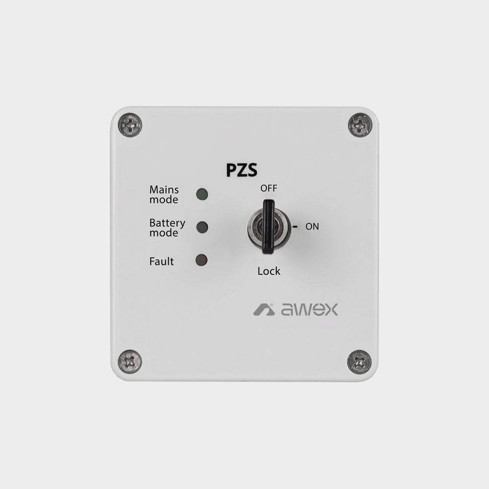
PZS modules
PZS-LON has built-in buttons for menu navigation and for locking all systems in the group. There are signaling diodes on the module: Network operation, Battery operation, Lockout, Error, additionally the PZS-LON module signals events with an acoustic signal.
| Technical Parameters | PZS | PZS-LON |
|---|---|---|
| Supply voltage | 24V DC | |
| Insulation class | III | |
| IP rating | IP41 | |
| Operating temperature range | -10 oC do + 40 oC | |
| Dimensions (SxWxG) | 82 x 82 x 55 [mm] | 130 x 100 x 37 [mm] |
| Number of CBS supported | 1 | do 10 |
| Communication | changeover contact | LON |
Files to download

Kitemark Certificate
pdf 0.77 MB
UEA Civil Defence
pdf 1.09 MB
CE Declaration
PDF 0.58 MB